Every plant that runs a pneumatic conveying system eventually has the same experience: the line stops, the pressure reading looks wrong, and the maintenance team starts checking components in whatever order feels fastest — usually starting with the fan, because it’s the biggest, loudest piece of equipment on the floor. That instinct is understandable, and it’s also almost always wrong. The component most engineers check last is the one actually responsible for the fault nearly nine times out of ten.
That mismatch between where operators look first and where the fault usually lives is the real cost driver behind conveying downtime. It’s not that pneumatic conveying systems fail more often than other bulk material equipment — it’s that when they do fail, plants without a structured diagnostic approach spend hours ruling out the wrong components before finding the right one. On a production schedule with committed order volume, every hour spent troubleshooting in the wrong direction is an hour the line isn’t running.
This breakdown covers the four core components of a pneumatic conveying system, the approximate failure-rate distribution across them based on field data, and the specific diagnostic indicators that point directly to the root cause — so troubleshooting becomes a process of elimination based on evidence, not a guessing exercise based on which component looks most suspicious.
The Four Core Components of a Pneumatic Conveying System
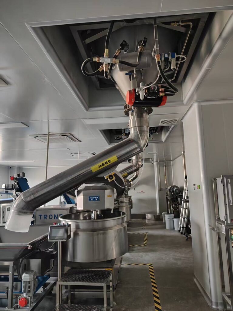
Every pneumatic conveying system, regardless of material or throughput, is built around the same four functional components:
- The fan unit, which generates the airflow that moves material through the system
- The conveying piping, which routes material from source to destination
- The filter receiver or bin vent, which separates conveyed material from the airstream at the destination
- The rotary valve, which meters material into or out of the airstream at the pressure boundary
Common symptoms across these four components include material buildup in piping or valves, unstable feed rate, elbow or valve wear, and an increasing frequency of pipe blockages. Where the fault actually originates, though, is far from evenly distributed across the four components — and that distribution is the key to troubleshooting efficiently.
Component 1: The Fan Unit (Approximately 1% of Faults)
When correctly sized and properly maintained, a fan unit is the most reliable component in the system — often running for two decades once it clears the first week of operation without issue. Belts may wear or occasionally fail, but rotational speed shouldn’t drift, and the pressure relief valve (PRV) shouldn’t activate under normal operation.
Diagnostic Indicator: Pressure Deviation
The fan’s pressure reading is the single best window into overall system health, and deviations point to specific fault categories:
- Pressure below normal typically indicates a feed fault upstream
- Pressure above normal typically indicates material buildup somewhere in the piping
- Erratic pressure swings typically indicate unstable feed rate or valve wear
- PRV trip or high-pressure shutdown typically indicates a pipe blockage
Before physically inspecting anything, pull the fan’s historical pressure trend from the control system. It’s the fastest, most reliable starting point for narrowing down where the actual fault lies.
Component 2: Conveying Piping (Approximately 5% of Faults)
Piping issues fall into two categories: material-driven wear and material buildup.
Wear Concentrates at Elbows
Abrasive wear on piping concentrates almost exclusively at elbows, where material impact is highest. Wear holes start pinhole-sized and gradually expand until material begins leaking through the wall — most commonly at the end of the conveying line, where velocity peaks, and this pattern shows up in both vacuum and pressure systems.
Buildup Shows Up as Pressure and Sound Changes
Material buildup inside piping presents as an abnormal pressure rise on the fan reading, combined with the absence of a detectable flow sound and vibration when a technician physically touches the pipe exterior — a simple field check that remains one of the fastest ways to confirm buildup without disassembling anything.
Component 3: Filter Receiver / Bin Vent (Approximately 5% of Faults)
The filter receiver’s job is gas-solid separation — not general dust collection — and it’s rated to specific pressure tolerances: 15 psig / 15 in. Hg for round housings, and 40 in. H₂O for square housings.
Common Fault: Filter Bag or Cartridge Fouling
A stable differential pressure reading with visibly dirty filter media is normal operating behavior. Fluctuating differential pressure, on the other hand, indicates the filter needs cleaning or replacement — that instability, not surface dirt alone, is the actual fault signal.
Common Fault: Solenoid or Diaphragm Valve Failure
A properly functioning cleaning pulse produces a sharp, consistent sound with every cycle. Any deviation from that consistent sound pattern indicates valve damage.
Diagnostic Focus: The Timer Control Board
The timer control board is the diagnostic center for this component. It controls pulse-cleaning duration and interval, displays filter differential pressure as a fouling indicator, supports on-demand cleaning mode, provides a dry-contact switch for high-pressure alarms, and outputs a 4–20mA signal for continuous monitoring.
Maintenance Note
Regularly inspect, clean, and replace the pressure-sensing media on filter instrumentation to ensure the differential pressure signal transmits accurately — a fouled sensing line will produce misleading readings regardless of actual filter condition.
Component 4: The Rotary Valve (Approximately 89% of Faults)
This is where troubleshooting should start, not end. The rotary valve is a precision component that typically operates in one of the harshest environments in the system, wears gradually, and — unlike the fan or filter — has no built-in predictive monitoring to flag degradation before it causes a failure. That combination is exactly why it accounts for the overwhelming majority of conveying system faults.
| Symptom | Underlying Cause |
|---|---|
| System throughput declining | Rotary valve wear |
| Frequent pipe blockages | Material buildup in rotor pockets |
| Erratic fan pressure swings | Unstable feed rate from the valve |
| Unusual valve noise (squealing, cracking) | Material buildup on interior valve walls |
Because rotary valve wear has no automated early warning, the diagnostic burden falls on scheduled physical inspection — checking rotor clearance and looking for material buildup before it produces one of the symptoms above.
Troubleshooting Priority: Where to Look First
Given the failure-rate distribution across these four components, an efficient diagnostic sequence looks like this:
- Check the rotary valve first — it accounts for nearly nine out of ten faults, and physical inspection here resolves most issues before they escalate.
- Check for piping buildup or elbow wear second — using pressure trends and the physical touch test.
- Check filter differential pressure and cleaning cycle behavior third — fluctuating pressure or inconsistent pulse sound points here.
- Rule out the fan last — it’s the most reliable component and the least likely source, despite often being the first place operators look.
Building Conveying Systems That Are Easier to Diagnose
Troubleshooting speed isn’t just a maintenance-team skill — it’s a function of how the system was engineered in the first place. WIJAY Systems designs pneumatic conveying systems with this failure-rate reality built into the engineering from day one: rotary valves specified for the actual material and duty cycle rather than a generic catalog part, pressure monitoring integrated into the control system so historical trend data is available at diagnosis time rather than reconstructed after the fact, and piping routed to minimize unnecessary elbow count at high-velocity points where wear concentrates fastest.
That design philosophy doesn’t eliminate maintenance — no conveying system runs maintenance-free indefinitely — but it does shift the maintenance burden toward scheduled, predictable inspection rather than unplanned emergency diagnosis, which is where most of the real downtime cost actually lives.
For plants evaluating a new pneumatic conveying system or troubleshooting persistent issues on an existing line, understanding this failure-rate distribution is the starting point for a faster, evidence-based diagnostic process — and for specifying equipment that reduces how often that process is needed in the first place.
FAQ
Which component of a pneumatic conveying system fails most often? The rotary valve accounts for approximately 89% of pneumatic conveying system faults, making it the component to inspect first during troubleshooting, ahead of piping, filters, or the fan unit.
How can I tell if a fault is coming from the fan or from downstream in the system? Pull the fan’s historical pressure trend from the control system. Low pressure typically points to a feed fault, high pressure typically points to piping buildup, and erratic swings typically point to unstable feed rate or valve wear.
What’s the difference between normal filter fouling and an actual filter fault? A stable differential pressure reading with visibly dirty filter media is normal. Fluctuating differential pressure is the actual fault indicator and typically means the filter bag or cartridge needs cleaning or replacement.
How do I check for material buildup inside conveying piping without disassembling it? Look for an abnormal pressure rise on the fan reading, then physically touch the pipe exterior — the absence of detectable flow sound and vibration confirms buildup at that section.
Can rotary valve wear be predicted before it causes a system fault? Rotary valves typically lack built-in predictive monitoring, which is why scheduled physical inspection of rotor clearance and buildup is the primary way to catch wear before it produces throughput loss or pipe blockages.