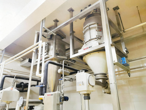
Every plant manager running powder or bulk solids has experienced the same scenario: production is running, the silo is full, and the line goes down because nothing is coming out. Or material trickles out intermittently, the feeder surges, and the downstream process goes out of spec before anyone can react.
These aren’t equipment failures in the conventional sense. They are flow failures — and they are almost always preventable with the right combination of material knowledge, equipment design, and operational discipline.
The Four Bulk Powder Flow Failures That Shut Down Lines
1. Arching (Bridging)
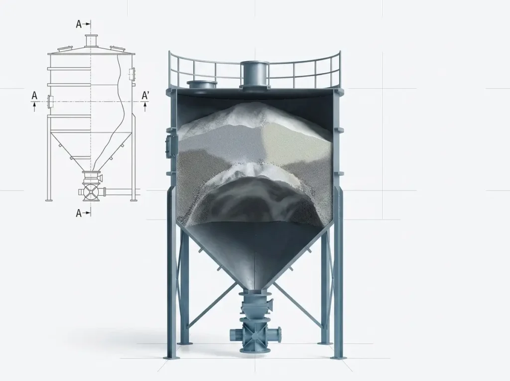
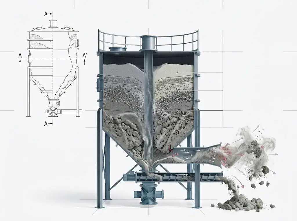
Arching occurs when powder or bulk solid forms a stable dome across the outlet of a hopper or silo, completely blocking discharge. The material above the arch remains stationary, no matter how long the system runs.
What causes it: Cohesive arching is driven by inter-particle forces — moisture, electrostatic charge, van der Waals adhesion — that are strong enough to support the weight of material above. Mechanical arching occurs when particle size is too large relative to the outlet diameter, causing physical interlocking. The two mechanisms feel identical from the outside (nothing flows) but require different corrective actions.
Field identification: Tap the hopper wall near the outlet zone. A hollow sound indicates a stable arch has formed and the material above has emptied. A solid sound means the material column is intact — the problem is elsewhere. Check outlet diameter against your D95 particle size; if the ratio is below 6:1 for granular materials or 10:1 for cohesive powders, the outlet is undersized by design.
What fixes it — short term: Air knockers or pneumatic vibrators on the cone section can break a cohesive arch temporarily. Bin activators (mechanical fluidizers mounted at the hopper outlet) provide continuous arch prevention for many materials. These are operational tools, not design corrections.
When you need to redesign: If arching recurs under normal production conditions — not just during startup after a long idle period — the outlet is too small or the hopper half-angle is too steep for the material’s flow function. Correcting this requires either increasing the outlet diameter or switching to a mass flow hopper geometry based on measured wall friction and flow function data. Operating adjustments alone will not provide a permanent fix.
2. Ratholing
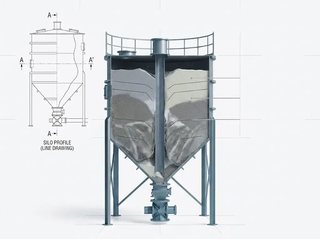
Ratholing is the inverse of arching. Material flows through a narrow channel directly above the outlet while the surrounding bulk remains stationary and consolidated. The funnel-flow channel eventually empties, flow stops, and the stagnant outer mass may never discharge — leading to material degradation, caking, and quality problems on top of the flow disruption.
What causes it: Funnel flow hopper geometry. In a funnel flow silo, material flows in a central channel while dead zones form at the walls. Any powder with sufficient cohesive strength will rathole in funnel flow geometry. The critical rathole diameter is a function of the material’s unconfined yield strength at the consolidation stress it experiences in storage — which increases with storage time, moisture uptake, and temperature cycling.
Field identification: Monitor discharge rate over time during a continuous draw-down cycle. Ratholing typically presents as a progressive reduction in flow rate that eventually stops before the silo is empty — sometimes with 30–60% of the material still inside. Probing the silo with a rodding tool confirms a hollow center channel with compacted surrounding mass.
What fixes it: For mild ratholing in materials with low cohesive strength, fluidization air pads or continuous low-level vibration can maintain flow in the dead zones. For cohesive powders — hydroscopic chemicals, fine food ingredients, pharmaceutical excipients — the geometry must be corrected. Converting from funnel flow to mass flow requires either a hopper insert (retrofittable in some configurations) or a full hopper replacement with the correct wall angle and surface finish to promote wall slip.
3. Erratic Discharge and Feeder Surging
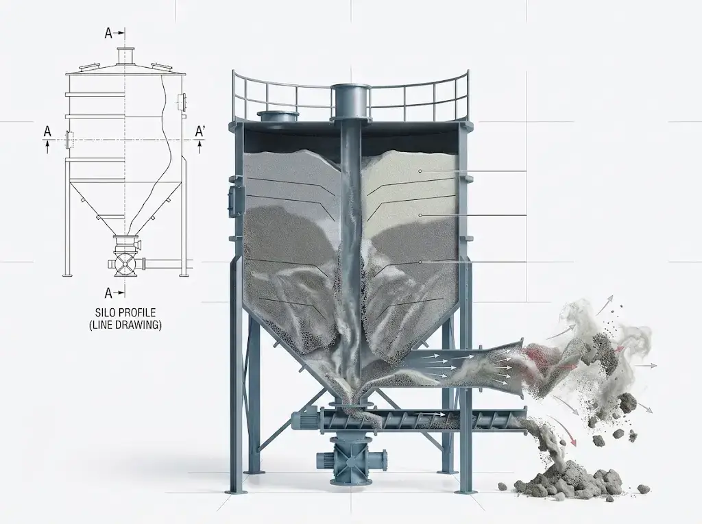
Even when material is flowing, an inconsistent flow rate creates downstream problems: overloaded conveyors, out-of-spec blend ratios, overfilled packaging, and intermittent blockages in downstream pneumatic lines.
Root causes — in order of frequency:
Feeder inlet flooding. A screw feeder receiving a head of fine powder will flood if the screw pitch is constant along its length. Material packs into the inlet section and surges in slugs. Correction: variable-pitch screws with a short pitch at the inlet, opening to full pitch at the discharge end. This is a design fix, not an operational one.
Hopper-feeder interface mismatch. If the feeder inlet does not span the full outlet of the hopper, a flow channel forms over the active section of the feeder, leaving stagnant zones that intermittently collapse into the active zone. The result is surge-and-starve cycling. The feeder must be sized to match the full outlet dimension of the hopper.
Segregation at the hopper outlet. If the incoming material separates by particle size during filling, coarser and finer fractions concentrate in different zones of the hopper. As the hopper empties, the ratio of coarse to fine in the discharge stream shifts progressively — causing density variations that appear as feeder surging but are actually a quality problem upstream of the feeder.
Excess air ingestion in pneumatic conveying lines. In dilute phase pneumatic systems, erratic feed from the rotary airlock valve creates slug flow in the pickup zone, which propagates as pressure fluctuations through the entire line. Check rotary valve clearances and tip speed; worn tip seals allow air bypass that disrupts steady-state conveying conditions.
4. Segregation, Flooding, and Material Buildup
Segregation during hopper filling is driven by particle size and density differences. Fine particles percolate downward through coarser material; aeratable fine powders can be carried to the outer walls during filling while coarser material settles centrally. The result is spatial separation of blend components that downstream mixing cannot correct.
Prevention, not remediation, is the only effective strategy. Mass flow hopper geometry enforces first-in, first-out discharge that dramatically reduces segregation potential. Inlet baffles that spread the fill stream across the full hopper cross-section also reduce the differential velocity that drives particle percolation.
Flooding occurs when aerated fine powder enters a feeder or outlet device faster than it can be metered. The powder behaves like a liquid — it flows uncontrolled, bypasses the feeder, and overwhelms downstream equipment. Flood gate valves upstream of the feeder and controlled deaeration of fine powders before the metering point are the standard countermeasures.
Wall buildup — material adhering to hopper walls and accumulating in dead zones — is a hygiene problem in food and pharmaceutical environments and a quality problem wherever product specifications are tight. It is caused by high wall friction combined with cohesive material behavior. Polished stainless steel with Ra ≤ 0.8 µm is the standard for food and pharma; electropolished surfaces or PTFE coatings address extreme adhesion cases. Smooth walls alone are not sufficient if the hopper geometry creates dead zones — the two must be addressed together.
Mechanical vs. Pneumatic vs. Vibratory Systems: Diagnosing Flow Problems by Conveying Mode
Mechanical Conveying (Screw, Belt, Chain)
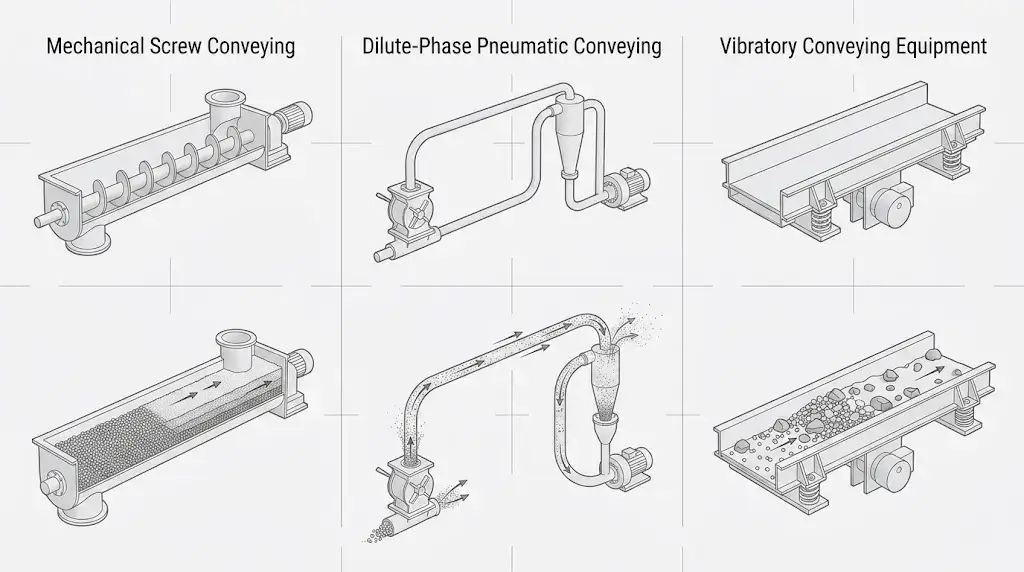
Flow problems in mechanical conveying systems typically originate at the feed point or at direction changes. Screw conveyors overfill and stall when the inlet receives more material than the screw can accelerate to operating speed — a condition worsened by fine, aerated powders with low bulk density. Chain conveyors see material packing at the base of vertical sections. In both cases, the diagnostic is simple: measure inlet feed rate against conveyor capacity rating under actual material conditions, not theoretical bulk density from a data sheet.
Pneumatic Conveying
Dilute phase systems are velocity-critical. Flow problems almost always trace to either insufficient pickup velocity (material settles and builds up in horizontal sections, then dislodges as slugs), excessive velocity (material degrades, fines generation increases, and filter differential pressure rises until the system pressure-balances against the fan curve), or a rotary valve that is no longer sealing reliably. Monitor pressure at three points: pickup, mid-line, and terminal receiver. A rising pickup pressure with stable mid-line and terminal pressure indicates an accumulation problem in the horizontal sections. A rising terminal pressure indicates filter loading.
Dense phase systems fail differently. Plug formation pressure and plug clearing time are the key indicators. If plugs are clearing but cycling frequency is increasing, material is being consolidated inside the line — typically from moisture uptake or from conveying at too low a pressure with too high a solids loading ratio.
Vibratory Conveying
Vibratory feeders and conveyors lose feed rate consistency when material properties change — moisture content shifting after process changes, particle size distribution broadening due to upstream grinding variation, or temperature changes that affect cohesivity. The trough amplitude and frequency are set for a specific material condition; changes in material behavior without corresponding control adjustments cause either sluggish transport or flooding. Check that vibration parameters are validated against the actual material specification range, not a single nominal condition.
Operational Adjustments vs. Equipment Modification: A Decision Framework
Not every flow problem requires capital expenditure. The following framework applies across most bulk powder handling scenarios:
Fix through operational adjustment:
- Arching or ratholing that occurs only after extended idle periods (weekend shutdowns, holiday stops) → implement scheduled activation cycles before startup
- Erratic discharge due to feeder speed settings not matched to actual bulk density → recalibrate feeder against current material
- Segregation worsening after raw material supplier change → re-evaluate filling rate and inlet geometry against new PSD
- Pneumatic conveying blockages triggered by seasonal humidity → install inline dew point monitoring and adjust conveying air dryer setpoints
Requires equipment modification or replacement:
- Arching or ratholing occurring under continuous normal production → outlet is undersized or hopper geometry is wrong; redesign required
- Feeder surging from constant-pitch screw inlet → variable-pitch screw replacement required
- Persistent segregation in blend-critical applications → mass flow hopper conversion required
- Chronic filter blinding in pneumatic system → filter media selection or can velocity is wrong; redesign or replace
The operational/modification boundary is not about cost — it is about whether the root cause is a process variable (correctable through adjustment) or a design variable (correctable only through redesign). Misidentifying the cause wastes time and money on operational measures that cannot address the underlying geometry or equipment mismatch.
Design and Operational Best Practices for Stable Powder Flow
- Characterize before you specify. Bulk density (at rest, tapped, and aerated), particle size distribution, angle of repose, wall friction angle, flow function, and moisture sensitivity are the minimum data set for any hopper or conveying design. Systems specified from datasheet values without actual material testing routinely require retrofit within 18 months of startup.
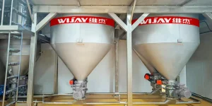
- Design for mass flow wherever product quality, hygiene, or first-in-first-out discharge matters. Mass flow hopper geometry — defined by the combination of hopper half-angle and wall friction angle that produces plug flow to the outlet — eliminates dead zones, reduces ratholing risk, and minimizes segregation during drawdown. The geometry is specific to each material; it cannot be approximated.
- Size the feeder inlet to match the full hopper outlet dimension. Partial-width feeder inlets create dead zones and surge cycling. This is one of the most common design errors in powder handling systems and one of the most consistently overlooked.
- Match pneumatic conveying mode to material properties, not pipeline distance. Fragile, high-value, or abrasive materials belong in dense phase. Fine, free-flowing powders with low bulk density may convey more reliably in dilute phase. Using the wrong mode for the material produces flow problems that cannot be resolved through operational adjustment.
- Validate under production conditions, not laboratory conditions. Material properties change with temperature, humidity, storage time, and upstream processing variation. System design should be validated against the worst-case material condition, and monitoring should be in place to detect when actual conditions diverge from design assumptions.
At Wijay Systems, every bulk powder handling project starts with a material characterization phase — including flow function testing, wall friction measurement, and moisture sensitivity analysis — before any equipment is specified. This data drives hopper geometry, feeder selection, conveying mode, and automation strategy. The entire integrated system — silo, feeder, conveying line, and dust management — is factory acceptance tested as a complete unit before shipment, validating flow performance under simulated production conditions. It is how flow problems get eliminated at the design stage rather than discovered at startup.
FAQ: Bulk Powder Flow Troubleshooting
Q: How do I tell the difference between arching and ratholing in the field without opening the silo?
Monitor the relationship between hopper weight (if load cells are installed) and discharge rate. Arching stops discharge while hopper weight remains static — the arch is supporting the full material column. Ratholing shows progressive discharge rate reduction with hopper weight declining, because the center channel is emptying while the surrounding mass stays put. If load cells are not installed, acoustic level sensors positioned at multiple heights on the hopper wall will detect the void pattern characteristic of each failure mode.
Q: Our powder flows fine in summer but blocks in winter. What’s happening?
Temperature affects two material properties simultaneously: cohesive strength (which typically increases as temperature drops and material contracts) and moisture behavior (cold walls can cause condensation that increases surface adhesion). The most common cause is that the material’s flow function is acceptable at summer operating temperatures but crosses into non-flowing territory at winter conditions. Run flow function tests at both temperature extremes. If the difference is confirmed, you have three options: heat-trace the hopper and silo to maintain a minimum wall temperature, modify the hopper outlet geometry to handle the worst-case flow function, or install a more aggressive flow promotion device sized for winter material conditions.
Q: We recently changed raw material suppliers and now have segregation problems we didn’t have before. Why?
Particle size distribution is almost certainly the cause. Segregation potential is driven by the ratio of coarse to fine particles and the spread of the size distribution. A broader PSD from a new supplier — even if the mean particle size is nominally the same — creates more percolation segregation during hopper filling. Run a side-by-side sieve analysis of the old and new material. If the PSD has broadened at either tail, that is your cause. Solutions range from changing the hopper fill point to use a central inlet with a cone diffuser (which spreads the fill stream and reduces size-differential velocity) to specifying mass flow geometry that minimizes the segregation that reaches the discharge stream.
Q: How often should pneumatic conveying system components be inspected for wear?
For dilute phase systems conveying abrasive materials, bend inspection should be part of a quarterly preventive maintenance cycle. Radiographic or ultrasonic thickness measurement at the outside radius of all elbows gives direct wear rate data without requiring system shutdown. For dense phase systems, wear rates are lower but pressure vessel certification intervals and rotary valve tip clearance checks are the critical maintenance items — typically annually or per manufacturer recommendation, whichever is more frequent. Keeping a wear log with thickness measurements at each inspection allows wear rate trending that predicts remaining service life rather than reacting to through-wall failures.
Q: Our screw feeder is rated for 500 kg/hr but we’re only getting 200 kg/hr consistently. What should we check first?
Start with the actual bulk density of the material at the feeder inlet versus the design bulk density used for the rated capacity. Screw feeder capacity is a volume calculation multiplied by bulk density — if the material is arriving aerated (after pneumatic transfer, for example) at 60% of its packed bulk density, the mass throughput will be proportionally lower. Second, check the inlet flood condition: if material is not gravity-filling the inlet cross-section consistently, the screw is running partially empty. Third, verify the screw speed is actually reaching its setpoint — VFD faults or mechanical slip in the drive train will reduce actual speed below commanded speed without triggering an obvious alarm. These three checks resolve the majority of screw feeder underperformance cases.
Work With Wijay Systems on Your Powder Flow Challenge
Flow problems in bulk powder handling systems are almost always diagnosable — and almost always preventable when systems are designed around the material rather than around a generic equipment catalogue.
Wijay Systems designs and supplies integrated bulk material handling systems for food, chemical, pharmaceutical, plastics, and new energy applications. Our project process begins with material characterization, works through equipment selection and system engineering, and validates performance through factory acceptance testing before any equipment reaches your plant.
If your current system is producing arching, ratholing, erratic feed, or segregation — or if you are specifying a new powder handling line — contact our engineering team to discuss your material and process requirements.
Submit your powder handling application to Wijay Systems →
Related reading