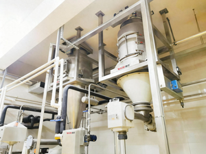
Most conveying system failures don’t start with a mechanical breakdown. They start months earlier, in a specification meeting, when someone selects dilute phase because it’s cheaper upfront — for a material that will shed 2% fines per pass, choke the pipeline every third shift, or grind through elbow sections in under a year.
Dense phase and dilute phase are not simply “slow” and “fast” variants of the same system. They operate on fundamentally different physical principles, carry different pressure requirements, serve different material profiles, and deliver different long-term economics. Getting the selection right at the design stage is one of the highest-leverage engineering decisions in a bulk handling project.
What Actually Defines Dense Phase and Dilute Phase
The boundary between these two conveying modes is defined by solids loading ratio (SLR) — the mass of material transported per unit mass of conveying air.
- Dilute phase operates at SLR below roughly 15:1. Material is fully suspended in the air stream, traveling at 18–40 m/s in a continuous, homogeneous flow.
- Dense phase operates at SLR above 15:1, commonly ranging from 30:1 to 100:1 or higher. Material moves at 2–10 m/s in slugs, plugs, or a moving packed bed — not in suspension.
The conveying velocity difference between these two modes is not incremental. It is the entire basis of their distinct performance profiles.
Key Operating Parameters at a Glance
| Parameter | Dilute Phase | Dense Phase |
|---|---|---|
| Conveying velocity | 18–40 m/s | 2–10 m/s |
| Solids loading ratio | < 15:1 | 15:1 to 100:1+ |
| System pressure (positive) | 0.5–1.1 bar | 2.0–9.0 bar |
| Typical blower type | Roots/vortex blower | Screw compressor |
| Material flow mode | Suspended, continuous | Slug, plug, or moving bed |
| Energy use (kWh/tonne) | 12–18 | 6–10 |
| Component wear rate | Higher | Lower |
| Capital cost | Lower | Higher |
The Hidden Cost of Choosing Dilute Phase for the Wrong Material
Here is where most project specifications fail in practice.
Dilute phase is widely favored because the capital cost is 30–50% lower than an equivalent dense phase system. The blower is smaller, the pressure rating is lower, and the control system is simpler. On paper, it closes the budget. In the plant, it can destroy that budget advantage within 18 months.
Fines generation. At conveying velocities above 20 m/s, inter-particle collisions and pipe wall impacts degrade friable materials continuously. For materials like battery-grade cathode powder, specialty polymers, or milled food ingredients, fines generation rates of 1–3% per conveying cycle are common in undersized dilute phase systems. At 8 t/hr throughput, that is 80–240 kg of saleable product converted to waste dust every hour of operation.
Elbow wear. Wear rate on pipe bends scales approximately with the cube of velocity. A system running at 30 m/s generates roughly 3.4× more elbow wear than one running at 20 m/s — and 125× more than a dense phase system running at 6 m/s. For moderately abrasive materials like titanium dioxide, silica flour, or recycled plastic regrind, standard carbon steel elbows at dilute phase velocities require replacement every 6–14 months. Dense phase operation on the same material can extend elbow service life to 4–7 years.
Pipeline blockage. Every dilute phase system has a minimum conveying velocity below which material drops out of suspension and begins to settle. That velocity must be maintained across the entire line length, including the pickup zone where velocity is always lowest. Fluctuations in feed rate, filter differential pressure, or upstream process conditions regularly push real-world operation below that threshold — particularly in systems that were specified with inadequate safety margins. Blockage recovery — manual rodding, pressure reversal, shutdown — costs an average of 2–4 hours of production per event.
Dense Phase: When Lower Velocity Changes the Entire System Economics
Dense phase conveying solves the velocity problem by moving material at a fraction of dilute phase speed, compensating through higher pressure and higher solids concentration per unit volume of air.
Why Dense Phase Suits Specific Material Profiles
Abrasive materials — silica, alumina, cement clinker, fly ash, mineral concentrates — generate elbow erosion proportional to velocity cubed. Dense phase keeps velocity below 8 m/s, which reduces wear rate by 90%+ compared to a 25 m/s dilute phase system. For a cement plant running 200 t/hr at 800 m distance, this wear reduction translates to maintenance savings of $80,000–$150,000 annually across a 20-year system life.
Fragile or high-value materials — lithium battery electrode powders, specialty catalyst pellets, pharmaceutical granules, compounded plastic masterbatch — cannot absorb the attrition losses that dilute phase generates. Dense phase at 3–7 m/s delivers these materials with minimal inter-particle contact. For battery-grade materials specifically, maintaining particle morphology throughout conveying is a direct quality compliance requirement, not a preference.
High bulk density materials (above 1,000 kg/m³) require disproportionately more air energy to maintain suspension in dilute phase. Dense phase bypasses the suspension requirement entirely, moving the material in a packed state and achieving 40–50% lower specific energy consumption versus dilute phase on the same duty.
Energy Gap Is Not Trivial
Across industries, the specific energy benchmark for dilute phase conveying runs 12–18 kWh per tonne of material transported. Dense phase consistently delivers 6–10 kWh per tonne on comparable duty cycles — a 40–50% reduction in conveying energy cost.
For a system running 8,000 hours per year at 10 t/hr average throughput, that energy differential amounts to 480,000–640,000 kWh per year. At $0.12/kWh industrial tariff, that is $57,000–$77,000 in annual energy savings. Over a 10-year system life, the dense phase capital premium is typically recovered two to four times over in energy savings alone — before accounting for maintenance, product loss, and downtime reduction.
Material Properties That Determine Mode Selection
Phase selection cannot be made from throughput and distance requirements alone. The material must drive the decision.
Particle Characteristics
Particle size sets the operating velocity floor. Materials with D50 below 100 microns — fine powders, pigments, carbon black — can be conveyed in dense fluidized phase at very low velocities. Coarser granules (D50 > 500 microns) require higher pickup velocities to initiate movement, which may push the system toward dilute phase for handling efficiency. Mixed particle size distributions behave differently from narrow distributions; the fine fraction creates inter-phase drag that assists suspension, while coarse fractions require more air momentum.
Bulk density is the primary energy scaling factor. Fine calcium carbonate at 400 kg/m³ and alumina powder at 1,100 kg/m³ require fundamentally different air volumes to achieve the same mass throughput. Ignoring bulk density in the initial sizing calculation typically results in an undersized blower that cannot sustain dilute phase suspension under full load — the most common cause of early-stage pipeline blockages in new installations.
Moisture content above 8–12% (material-specific) causes wall adhesion, plug formation, and bridging at pipe bends. This threshold varies significantly: hygroscopic materials like certain food starches and lithium salts respond to moisture at much lower levels than mineral powders. When ambient humidity or process moisture is a variable, the conveying system must be sized for worst-case conditions, not average conditions.
Abrasivity and fragility are often inversely related in industrial practice — coarser, harder materials tend to wear equipment; finer, lighter materials tend to degrade themselves. This divergence is exactly why dense phase exists: it protects the equipment for hard materials and protects the product for soft ones.
Quick Selection Reference
| Material Characteristic | Recommended Mode | Reason |
|---|---|---|
| Abrasive, high bulk density | Dense phase | Velocity-cubed wear law |
| Fragile, high-value | Dense phase | Fines generation control |
| Cohesive, moisture-sensitive | Dense phase | Lower velocity reduces bridging risk |
| Fine, free-flowing, low bulk density | Dilute phase | Suspension is efficient; dense phase may fluidize poorly |
| Non-abrasive, multi-pickup-point | Dilute phase (vacuum) | Topology flexibility; low pressure risk |
| Explosive dust hazard | Dense phase (with inert gas) | Reduced gas volume, lower oxygen inventory |
System Architecture: What Changes Between Modes
The pressure difference between modes is not just a number on a specification sheet. It changes the entire equipment selection and plant infrastructure.
Dilute Phase Equipment Stack
- Air mover: Roots blower or vortex blower, typically 0.5–1.1 bar gauge, 10–500 m³/min
- Feed device: Rotary airlock valve — allows continuous metered feed while sealing against system pressure
- Pipeline: Standard carbon steel or 304 SS for food/pharma; pipe diameter 50–200 mm for most duties
- Filtration: Pulse-jet fabric filter (baghouse) at the terminal receiver; typically sized for 1–3 m/s can velocity
- Controls: Pressure differential monitoring, rotary valve speed control, filter differential pressure management
Dense Phase Equipment Stack
- Air mover: Screw compressor or high-pressure Roots, 2.0–9.0 bar gauge; lower volumetric flow than dilute phase
- Feed device: Pneumatic pressure vessel (blow pot) or dense phase pump — batched or continuous configurations
- Pipeline: Heavier wall specification; wear-back elbows or ceramic-lined bends at direction changes
- Instrumentation: Pressure transducers at inlet, mid-point, and outlet; phase detection for slug/plug confirmation
- Controls: Boost air injection for line clearing; pressure profile management across conveying cycle
One architectural consideration that often goes unaddressed in competitor articles: dense phase systems operating in slug or plug flow generate pressure fluctuations that must be absorbed by the receiving vessel and downstream process equipment. Where a process silo or reactor vessel has pressure rating limitations, this must be factored into system design — particularly for back-pressure-sensitive pneumatic injection applications in cement and lime production.
Vacuum vs. Pressure: A Third Dimension
Both dense phase and dilute phase can operate in positive pressure (blower upstream, material pushed) or vacuum (pump downstream, material pulled) configurations. This choice is often dictated by plant topology rather than material properties.
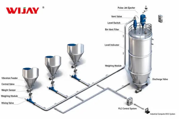
Vacuum systems (typically dilute phase) excel where material must be drawn from multiple pickup points — tanker truck unloading, multiple bag dump stations, silo bottom extraction. The negative pressure design means any leak draws in ambient air rather than pushing out product dust, which simplifies containment compliance. Maximum practical vacuum is around -0.9 bar gauge, which limits conveying distances to roughly 300–500 m in most industrial applications.
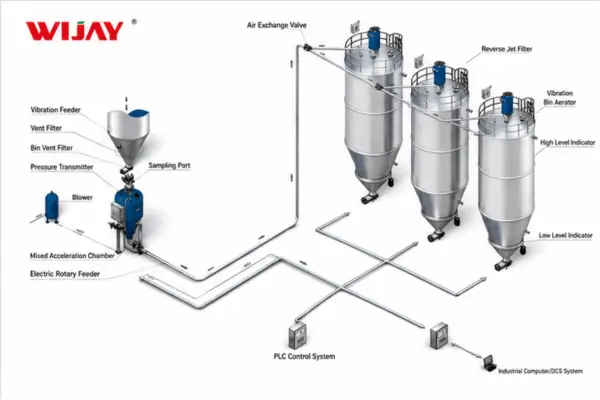
Positive pressure systems reach longer distances and achieve higher throughput rates but require full sealing at all material entry points. For toxic, explosive, or oxygen-sensitive materials — including lithium battery powders and certain specialty chemicals — positive pressure systems with inert gas purging (nitrogen) are the standard configuration, as they eliminate atmospheric oxygen from the conveying stream and reduce dust explosion risk.
Industry Application Matrix
| Industry | Typical Material | Preferred Mode | Wijay Project Notes |
|---|---|---|---|
| Food processing | Flour, sugar, starch, cocoa | Dilute phase (SS pipeline) | Hygienic design, CIP-compatible joints, ATEX rated for dust zones |
| Chemical | TiO₂, carbon black, catalyst pellets | Dense phase | Enclosed fully-sealed system, zero fugitive emission |
| Plastics | PE/PP pellets, regrind, masterbatch | Dilute or dense phase | Angel hair risk at >20 m/s; dense phase preferred for compounded grades |
| Lithium battery | Cathode/anode powders, LCO, NMC | Dense phase, N₂ purge | Morphology-critical transport; particle integrity FAT tested before shipment |
| Cement/minerals | Cement, fly ash, alumina, lime | Dense phase | Long distance (up to 2,000 m); high solids loading ratio |
| New energy materials | Silicon anode, electrolyte powders | Dense phase, sealed | Reactive materials require gas-tight fully-automated feed-discharge cycle |
The Conveying System is a Process Unit — Not a Utility
One persistent misconception in bulk handling project management is treating the pneumatic conveying system as a utility — like compressed air or cooling water — rather than as a process-critical piece of equipment. It gets specified late, budgeted at the commodity rate, and handed off to the lowest bidder.
The consequence is predictable. A conveying system mismatched to its material and process creates quality incidents, unplanned downtime, and maintenance spend that recurs for the life of the plant. The cost of a blockage event — labor, lost throughput, product exposure — typically exceeds the cost difference between a properly specified system and an underspec’d one within 12–24 months of operation.
At Wijay Systems, the approach to every bulk conveying project starts with material characterization — particle size distribution, bulk density at rest and aerated, angle of repose, moisture sensitivity, minimum conveying velocity testing, and attrition index measurement where relevant. The phase mode selection, blower sizing, pipeline layout, and automation strategy all follow from that data. This is not a sequential process; it is iterative, and the factory acceptance test (FAT) validates the complete integrated system under simulated production conditions before any equipment ships.
FAQ: Dense Phase vs. Dilute Phase Pneumatic Conveying
Q: Can I convert an existing dilute phase system to dense phase?
Conversion is technically feasible but rarely cost-effective without major infrastructure changes. The pressure vessel specification for dense phase (2–9 bar) versus dilute phase (0.5–1.1 bar) requires a complete replacement of the blower or compressor, the feed device, and typically the control system. Pipeline sections can sometimes be reused if their pressure rating is sufficient and bore diameter is appropriate. The economic case depends heavily on the energy and maintenance savings achievable post-conversion versus the capital cost of retrofitting. An independent system audit is strongly recommended before committing to conversion.
Q: What is the maximum conveying distance for each mode?
Dilute phase (positive pressure) is practically limited to 300–800 m depending on material and blower capacity. Vacuum dilute phase limits further to 150–500 m. Dense phase positive pressure systems regularly convey at 800–2,000 m, with some cement and mineral installations exceeding 2,500 m using intermediate booster stations. Vertical lift is more constraining than horizontal distance; 50–100 m vertical lift is typical for dilute phase, while dense phase systems handle 200–400 m vertical with appropriate pressure reserves.
Q: How does pipe diameter selection affect phase behavior?
Pipe diameter directly determines conveying velocity at a given volumetric air flow rate. Upsizing the pipe reduces velocity (beneficial for fragile materials, elbow wear) but also reduces the gas velocity needed to maintain suspension in dilute phase — which can trigger saltation and blockage. Downsizing increases velocity, improves pickup, but accelerates wear. For dense phase, pipe diameter determines plug length and slug frequency, both of which affect pressure cycling and feed device cycling rate. Optimization requires iteration between air volume, pipe size, and pressure reserve.
Q: What safety systems are required for fine powder conveying?
Fine powders with minimum ignition energy below 1,000 mJ require ATEX-rated equipment in Europe and NEC/IEC Ex classification in other markets. This includes explosion-proof motors, static-dissipative pipe joints, earthing of all conductive components, and rotary valve specifications that prevent flame propagation between upstream and downstream sections. For materials with minimum explosive concentration (MEC) below 60 g/m³, fully inerted conveying with oxygen monitoring is the safest configuration. Relevant standards include NFPA 654, EN 14460, and ATEX Directive 2014/34/EU.
Q: How do I determine if my material is suitable for dense phase without lab testing?
The Geldart classification is a practical starting point. Geldart Group A powders (fine, cohesive, aeratable — typically 20–100 micron) are generally suited to fluidized dense phase. Group B powders (coarse, sand-like, 100–800 micron) typically convey in dilute phase or plug flow dense phase. Group C powders (ultrafine, cohesive, prone to channeling) often require fluidization aids or dense phase with booster air injection. Group D materials (large, high-density particles) are generally not candidates for conventional dense phase and may require specialized fluidized bed pump systems. Laboratory pilot testing remains the most reliable validation method for materials with unusual characteristics.
Work With Wijay Systems on Your Conveying Application
If your project is at the stage where phase mode selection is still open — or if you are troubleshooting a system that is not performing to specification — the most productive starting point is a material characterization review combined with a system audit of the current or proposed configuration.
Wijay Systems designs and supplies fully integrated bulk material conveying systems across food, chemical, plastics and new energy industries. Our project workflow includes material testing, complete system engineering, factory acceptance testing of the integrated conveying line, and startup commissioning support. Every system ships with documented FAT results and a conveying performance guarantee referenced to the agreed material specification.
Submit your conveying application to the Wijay Systems engineering team →
Related Reading:
- The Role of Air Velocity in Optimizing Pneumatic Conveying Efficiency
- How to Reduce Energy Costs in Pneumatic Conveying Systems
- Pneumatic Conveying System Design for Lithium Battery Electrode Materials
- Minimum Conveying Velocity: How to Find It and Why It Defines Your Entire System
External References: