Every engineer who has worked with pneumatic conveying knows the feeling. The system ran fine last week. This week, throughput is down, the line is plugging every shift, and the maintenance crew is swapping out elbows faster than you can order replacements.
You check the blower. It’s running. You check the feeder. It’s feeding. But something is wrong.
Troubleshooting bulk powder conveying isn’t about guessing. It’s about understanding the physics of what’s happening inside the pipe — and knowing where to look when things go sideways.
This article addresses nine real-world questions that come up regularly in system design and troubleshooting. These aren’t textbook theory questions. They’re the ones engineers ask when they’re standing in front of a system that isn’t performing.
1. Starting from Scratch: How Do You Estimate the Required Conveying Line Diameter?
This is the first question every new system design faces — and it’s more iterative than most people expect.
The answer depends on one fundamental variable: how much pressure do you have available?
If you’re using a positive displacement blower, you’re limited to roughly 15 psi (≈103 kPa). With that pressure ceiling, you need a pipe diameter large enough to handle your material over the required distance, including all bends and changes in direction, while staying under that pressure limit.
If you’re using a single-stage compressor, you have more headroom — typically 40–45 psig (≈276–310 kPa) — which means you can use a smaller diameter pipe. The higher the pressure you can afford, the smaller the line diameter you can get away with.
The practical method:
- Assume a pipe diameter.
- Estimate the pressure drop for that diameter based on your air supply, conveying rate, line length, and bend count.
- Run the calculation.
- If the calculated pressure drop exceeds your available pressure, increase the diameter and recalculate.
- If the calculated pressure drop is far below your available pressure — say, you have a 3-inch pipe with only 2 psi drop — you can reduce the diameter.
This is an iterative process. Don’t expect to get it right on the first pass. And don’t assume that bigger pipe is always better — oversizing can lead to low velocity and saltation issues just as surely as undersizing leads to high pressure drop.
2. Rotary Valve Leakage: Static and Dynamic — Both Matter
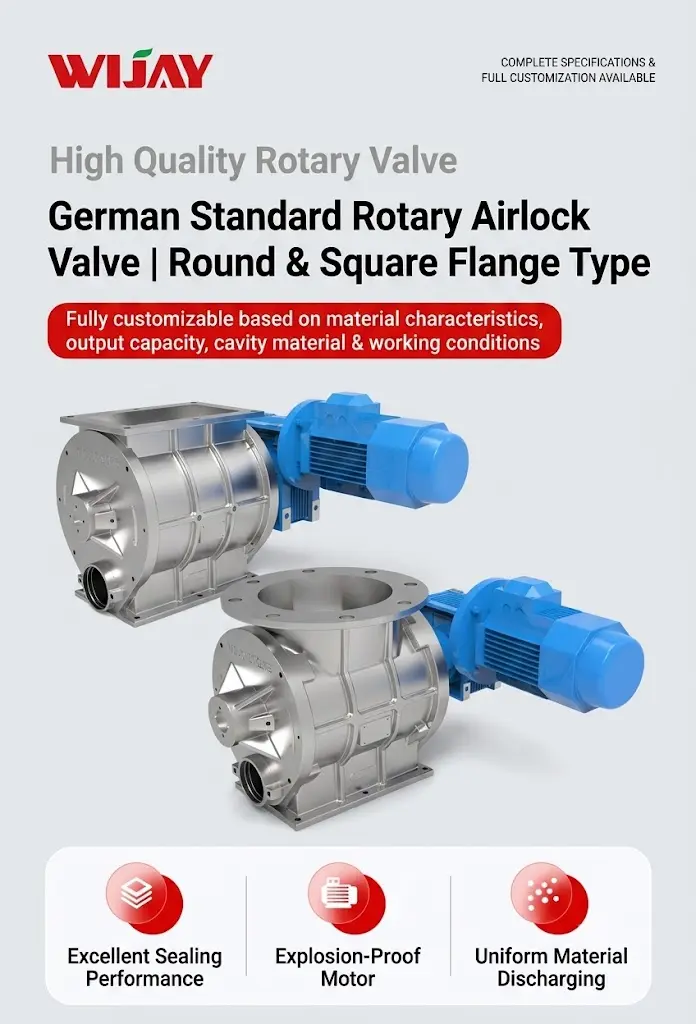
Rotary valves are the most common feeding devices in pneumatic conveying, but they’re also one of the biggest sources of air leakage. And leakage matters because it directly affects blower sizing.
The question: If you increase rotary valve speed and/or pressure, do you expect additional air leakage?
The answer: Yes. Significantly.
Air leakage through a rotary valve comes in two forms: static leakage and dynamic leakage.
Static leakage occurs through the clearance between the rotor tip and the valve body ID. It’s a function of differential pressure — the higher the pressure across the valve, the more air leaks through those clearances. Even if the feeder isn’t turning, static leakage is present as long as there’s a pressure differential.
Dynamic leakage happens when the rotor turns. Each pocket of the rotor carries a volume of compressed air (at line pressure) back to the inlet side and releases it during discharge. This volume — measured in ACFM converted to SCFM — must be added to the blower capacity calculation. The faster the valve turns, the more pockets per minute, the more dynamic leakage. Higher pressure also increases the density of the air in each pocket, compounding the effect.
The practical takeaway: When you increase rotary valve speed or system pressure, you’re not just moving more material — you’re also adding air leakage that must be accounted for in blower sizing. Many systems are undersized precisely because this dynamic leakage wasn’t included in the original calculation.
3. Where Do You Find Saltation Velocity Data?
Saltation velocity is the gas velocity at which fully suspended particles in a horizontal conveying line begin to drop out of suspension and settle on the bottom of the pipe. Below this velocity, the material stops flowing as a suspension and starts forming a layer — and that layer is the beginning of a plug.
The short answer: There’s no single lookup table.
Saltation velocity depends on particle diameter, terminal velocity, particle-wall friction, and solid loading ratio. Different materials behave differently. Different formulas exist from researchers like Zenz, Risk, Weber, and Klinzing — each with different assumptions and applicability ranges.
The practical approach:
- Start with published correlations for your material type.
- Use saltation velocity as your lower bound for conveying velocity in horizontal runs.
- Recognize that saltation velocity is a starting point, not a final answer.
The better approach: Test your actual material. Laboratory conveying tests on your specific powder will give you real saltation data for your particle size distribution, moisture content, and bulk density. Many engineers skip this step and pay for it later with plugging problems.
4. Not Enough Blower Capacity? Parallel Blowers Have Rules
When a system needs more air than a single blower can provide, the instinct is often to replace it with a larger unit. Sometimes that’s the wrong move.
If you need only about 30% more air, don’t double the blower size. Add a second blower of the same size in parallel.
Here’s the logic:
- Two identical blowers in parallel each deliver half the total airflow.
- They see the same back pressure, so both operate on their published performance curves.
- Spare parts are interchangeable — one part number for both units.
The critical detail: Inlet and discharge piping must be symmetrically designed to prevent flow bias. If one blower has a longer or more restrictive inlet path than the other, it will draw less air and the other will work harder — potentially overload it. Keep the piping runs identical.
5. Stepped Pipe: How Much Straight Run After a Bend Before You Increase Diameter?
Stepped pipe design — increasing the pipe diameter partway along the conveying line — is one of the most effective ways to control velocity and reduce wear. But placement matters.
The rule: Allow 6 to 10 pipe diameters of straight run after each bend or change in direction before stepping up the diameter.
- For dilute phase conveying, use the 10‑diameter guideline.
- For dense phase or mixed flow, 6 to 10 diameters is acceptable.
- Never place a step immediately after a bend. The material stream needs distance to re-establish a stable flow pattern after the disturbance of the bend.
The ideal location: A vertical section 10 to 20 feet (≈3–6 m) after a bend, where the material and air are fully re‑entrained.
If you must step in a horizontal section, use an eccentric reducer with the bottom of the pipe kept level. This maintains support and prevents material from settling in a low spot.
6. Does More Air Always Mean More Wear?
No. This is one of the most persistent misconceptions in pneumatic conveying.
Wear is a function of velocity, not volume.
If you increase air volume without increasing pipe diameter, velocity increases — and wear accelerates dramatically.
But if you increase pipe diameter along with the air volume — through stepped pipe design — the expanded air has more cross‑sectional area to flow through, so velocity stays controlled or even decreases.
Example: Conveying an abrasive material in a 6‑inch (152 mm) line. Without stepping, the velocity naturally increases as air expands along the line, so the downstream sections see much higher velocities — and much higher wear — than the upstream sections. With proper stepping to a larger diameter downstream, the velocity drops back to a manageable range, and wear is distributed more evenly.
The principle: Add air if you need capacity, but always step the pipe diameter to control the resulting velocity. More air is not the enemy — uncontrolled velocity is.
7. Dense Phase vs. Dilute Phase: Which One When?
This is the fundamental decision in pneumatic conveying system design. The choice isn’t about which is “better” — it’s about which is appropriate for your material and application.
The guidance:
- Dilute phase is the default. It works for almost everything. But if your material is abrasive, it will wear out the pipe. If it’s fragile, it will break.
- Dense phase is the specialty choice. It’s gentler on the material and kinder to the pipe — but it’s not suitable for all materials. Some powders won’t form stable plugs. Some are too cohesive.
The practical recommendation: If you’re considering dense phase, do a simple test early. Before committing to a commercial system, have multiple dense‑phase system suppliers run actual conveying tests on your material in their labs. Theory only takes you so far — real material behavior in a real pipe is the only thing that matters.

8. What Velocity Should You Maintain in the Pipe?
Velocity management is the single most important design parameter in pneumatic conveying. Get it wrong, and nothing else matters.
The approach:
- Start with saltation velocity — the minimum velocity required to keep material suspended in horizontal runs.
- Add a margin to get pickup velocity — the velocity at the feed point, slightly above saltation, needed to entrain the material into the airflow.
- As air expands along the pipe, velocity naturally increases.
- Step the pipe diameter at appropriate points to keep velocity from running away.
The critical insight: If you keep the same pipe diameter from start to finish, the velocity at the end of the line can be double or more what it was at the pickup point. That means the last bend sees twice the velocity of the first bend — and wears out twice as fast. Products that are fragile get shattered at the end of the line.
The solution: Map the velocity profile along the entire line. Step the diameter to keep velocity within a controlled range — high enough to prevent saltation, low enough to prevent excessive wear and degradation.
Velocity optimization is not optional. It’s the difference between a system that runs for years and one that fails in months.
9. Can You Use Inclined Pipe Runs?
Yes — but with conditions.
The best practice: Use horizontal + vertical combinations. Avoid inclined runs whenever possible.
If you must use an incline:
- Inclines less than 15° can be treated approximately as horizontal or vertical, depending on the orientation. The pressure drop penalty is minimal.
- Inclines approaching 45° require additional pressure drop calculation. The velocity distribution in that section must be reviewed carefully.
Positioning matters. If you need an upward inclined section, place it near the end of the system, close to the discharge point. Velocity is naturally higher at the end of the line (due to air expansion), so the material has more momentum to overcome the incline. An upward incline at the beginning of the line, where velocity is lowest, is a recipe for plugging.
The Bigger Picture: Systematic Troubleshooting
These nine questions cover the most common pain points in pneumatic conveying — but they’re not a checklist. They’re a diagnostic framework.
When a system fails, the root cause is almost always one of these:
- Incorrect velocity — too low causes saltation and plugging; too high causes wear and degradation
- Inadequate air supply — often because rotary valve leakage wasn’t accounted for
- Poor pipe layout — bends too close together, improper stepping, or problematic inclines
- Wrong conveying mode — dense phase specified for a material that won’t plug, or dilute phase for a material that can’t handle the velocity
The cost of guessing is measured in downtime, replacement parts, and lost production. The cost of understanding is measured in engineering hours and material testing.
Choose understanding.

Why WIJAY for Your Bulk Powder Conveying Challenges?
At WIJAY, we don’t sell generic conveying equipment and hope it works. We engineer complete material handling systems based on the actual behavior of your powder — not on assumptions.
With over 12 years of experience in powder and bulk material handling, a 2,000 m² R&D center, and more than 50 invention patents, WIJAY delivers:
- Integrated line solutions — from storage and feeding to conveying and batching, one partner handles the whole system
- Enclosed, dust‑free conveying — negative‑pressure or positive‑pressure systems that contain material and eliminate fugitive dust
- Low‑loss, high‑efficiency design — engineered to minimize product degradation and material waste
- Full automation — PLC‑controlled systems with real‑time monitoring and diagnostics
- Multi‑industry expertise — food, pharmaceutical, chemical, battery materials, and more
Whether you’re designing a new line or troubleshooting an existing system, WIJAY’s engineering team has the practical experience to get it right.
Want to learn more about how WIJAY can solve your bulk powder conveying challenges? Visit www.wijaysystems.com to explore our full range of pneumatic conveying systems, integrated material handling solutions, and custom‑engineered equipment. Our engineering team is ready to help you design a system that works — reliably, day after day.