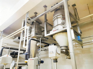
If you’ve ever had a rotary valve on your line fail early, leak air across a supposedly sealed interface, or jam without warning, you already know the frustration: it’s one of the simplest pieces of equipment in the plant, and yet it’s one of the most common sources of unplanned downtime in bulk solids handling. A rotor turning inside a housing shouldn’t be this hard to get right — and yet, across the industry, “unreliable rotary valve performance” is one of the most repeated complaints plant engineers raise, often prompting a search for alternative equipment that, in most cases, never fully delivers on the promise.
That’s not because rotary valves are inherently flawed. It’s because most valves in service were selected on throughput numbers alone — tons per hour and not much else — without accounting for the product characteristics, pressure conditions, and duty cycle that actually determine whether that valve survives its expected service life. This rotary valve selection guide breaks down why that gap exists and what actually needs to be evaluated before a valve is specified.
Why Rotary Valves Keep Getting a Bad Reputation
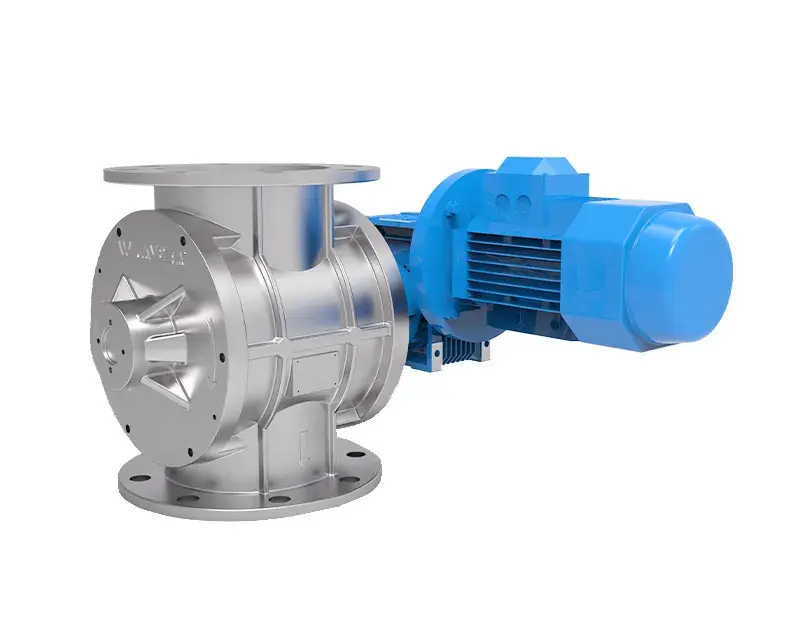
At their core, rotary valves are about as mechanically simple as bulk handling equipment gets: a multi-vane rotor is the only moving part, aside from the drive. They’re compact, economical, and have been in continuous industrial use since the early 20th century, when they were first applied to grain and other easily handled bulk food products. Over the decades they’ve picked up a handful of names — rotary airlock, star valve, rotary seal, blow-through valve — but the function has stayed largely the same: controlling the gravity discharge of powders and granular solids between two sections of a system, typically across a pressure differential.
The reputation problem isn’t the concept. It’s that unlike gases and liquids, bulk solids don’t behave with predictable, stable physical properties. Particle size, flowability, moisture content, and abrasiveness shift with environmental and production conditions — which makes reliable performance calculations far harder than they look on a spec sheet. A valve sized purely on weight-per-hour throughput, without factoring in how the actual material behaves inside the rotor cavity, is a valve that’s already at risk of underperforming before it’s even installed.
What a Rotary Valve Is Actually Being Asked to Do
Beyond simple flow metering, a properly specified rotary valve is frequently expected to perform several functions simultaneously:
- Control product flow to a fixed or variable target rate
- Maintain a gas pressure differential between inlet and outlet (airlock function)
- Act as an explosion containment device
- Serve as an autonomous safety barrier against flame and explosion propagation
- Function as a process isolation barrier
Each of those functions has to hold up while the valve is also handling difficult product characteristics shaped by process conditions, environmental exposure, and regulatory requirements. That’s a lot to ask of a single rotating component — which is exactly why selection deserves more rigor than throughput math alone.
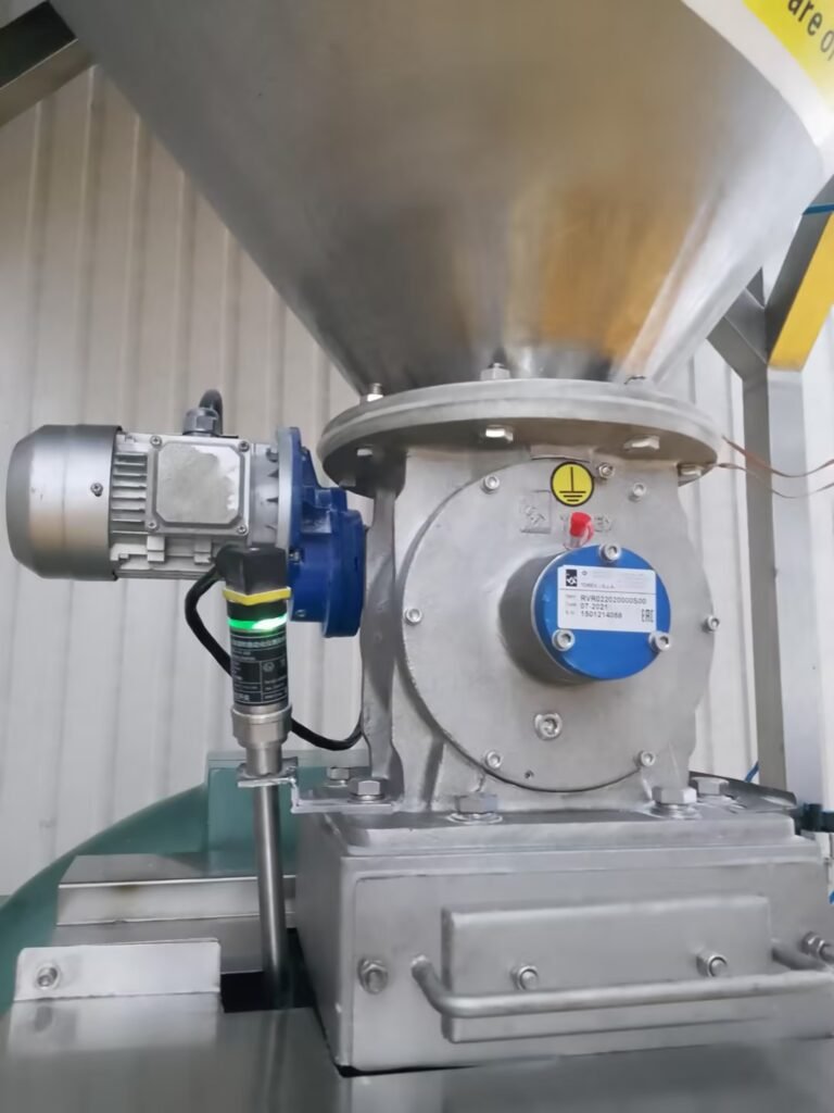
The Six Factors That Actually Determine Rotary Valve Performance
1. Sizing and Rotor Speed
Most customers specify required capacity in weight per hour — tons/hour, for example. Because a rotary valve is a volumetric discharge device, sizing has to work backward from throughput weight, product bulk density, and fill efficiency. Fill efficiency itself is shaped by rotor speed, the product’s flow characteristics, bulk density as it enters the rotor pocket, leakage effects, valve size, and inlet feed conditions.
As a general rule, rotor tip speed above roughly 40 meters per minute causes discharge output to drop, with performance becoming unstable as that threshold is approached — for reference, that’s about 85 rpm on a 150mm-diameter rotor, or 17 rpm on a 750mm rotor. For reliable, consistent discharge, most applications should specify a valve sized to keep rotor speed under 25 rpm for rotor diameters up to 300mm. Larger valves, with proportionally roomier throats, can safely operate closer to that 40 m/min tip speed. The final speed decision still has to account for the specific flow characteristics of the product being handled.
2. Product Characteristics
Product behavior defines component design and material selection — and this is where many “reliable elsewhere, problematic in a rotary valve” failures originate. Fine, mildly abrasive powders can become highly erosive when entrained in the high-velocity leakage that occurs across valve clearances. Temperature-sensitive products can plasticize from inter-particle friction inside those same clearances, degrading product quality. Others accumulate on working surfaces under interface pressure or moisture, generating unacceptable torque loads and audible noise. Food and pharmaceutical products require sanitary, easily cleanable construction, and any organic product handled as airborne dust carries explosion risk that has to be engineered for from the start — not addressed after an incident.
3. Differential Pressure
Differential pressure is one of the clearest indicators of whether a given valve design is suitable, because it’s the condition under which leakage becomes most likely. Higher differential pressure means higher leakage risk, which directly shapes final valve sizing and feature selection — and particle size and flow characteristics compound that effect further.
High leakage can significantly reduce material throughput by fluidizing and lowering bulk density, or by physically obstructing flow. In other cases, that same leakage can assist product flow by inducing agitation or fluidization. Either way, the net effect has to be accounted for during sizing — and the problem eases somewhat as valve size increases, since a larger throat allows leakage air to disperse more effectively.
Installation matters here too: a rotary valve should be mounted directly at a hopper outlet so leakage air can disperse freely. Anything less than free-fall, controlled cascading flow into the valve — i.e., the valve not operating in a flooded condition — tends to produce worse leakage outcomes. Whether to design around suppressing or actually utilizing that leakage should be settled with the engineering team before installation, not discovered after commissioning.
4. Temperature Conditions
Rotary valves are specified across an extreme range — from -80°C dry ice environments to continuous 960°C incinerator ash discharge into pneumatic conveying lines. What matters most isn’t just the absolute temperature, but whether the valve heats gradually during production or experiences thermal shock from a sudden influx of hot product. Under shock loading, a lighter rotor structure expands faster than a housing that’s simultaneously losing heat to the exterior. That means rotor clearances have to be set so they land at their optimal operating gap only once the system reaches steady-state temperature — which also means leakage will run significantly higher during the ramp-up period before that point.
5. Customer and Industry Requirements
Some operations only care that the valve performs to spec and lasts — that’s the entirety of the requirement. Others, and entire industries, carry substantially higher documentation, testing, and certification expectations layered on top of the base design. Depending on the application, that can mean extended inlet geometry and precisely angled cones for poor-flowing, low-density products; ultra-hygienic construction rated as an autonomous safety device for high-potency pharmaceutical handling; scraper-equipped rotor pockets that actively clear sticky product that wouldn’t discharge by gravity alone; stainless construction engineered as a process isolator rated for chlorine gas service under 7 bar internal pressure with 100 mbar differential; dual valves in series — either two sealed rotors minimizing leakage on very light, free-flowing product, or a metering/sealing pair where a reduced-capacity, wider-clearance upper rotor feeds a lower sealing rotor at a controlled rate to eliminate jamming; and heat-resistant valves rated for continuous 500°C service discharging ash and grit from fluidized bed dryers, with automatic reversing to clear blockages.
6. Regulatory Compliance
Beyond customer-specific requirements, valves also have to meet applicable regional directives and standards — covering machinery safety, pressure equipment, and explosion protection, along with sector-specific requirements for food and pharmaceutical handling. None of this is optional once a product or industry classification triggers it, and retrofitting compliance after installation is materially more expensive than specifying for it upfront.
Selection Is Judgment, Not Just a Spec Sheet
Successful rotary valve selection ultimately comes down to combining calculation with experience-based judgment. The majority of applications can be met through a standard range of configurations and common functional options — but a meaningful share of applications genuinely require custom engineering, and knowing which category a given application falls into is itself part of the expertise.
Frequently Asked Questions
What’s the most common reason rotary valves fail prematurely? Undersizing based on throughput alone, without accounting for product characteristics, differential pressure, and rotor speed limits, is the most frequent root cause of leakage, jamming, and early wear.
What rotor tip speed should a rotary valve run at? As a general guideline, tip speed above roughly 40 m/min causes discharge output to drop and performance to become unstable. Most applications on valves up to 300mm rotor diameter should be sized to keep speed under 25 rpm.
Does a rotary valve need to be installed directly under a hopper? Yes — mounting the valve directly at the hopper outlet allows leakage air to disperse properly. A flooded inlet, rather than controlled cascading flow, tends to produce worse leakage behavior.
Can one rotary valve handle both metering and sealing functions? In some configurations, yes — a series pairing with a reduced-capacity, wider-clearance upper rotor feeding a lower sealing rotor is a common way to achieve both metering and jam-free sealing in a single assembly.
Do rotary valves need explosion protection? Any application handling organic product that can become airborne as combustible dust needs the valve engineered for explosion containment or as an autonomous safety device from the design stage — not retrofitted after the fact.
Where WIJAY Fits Into This
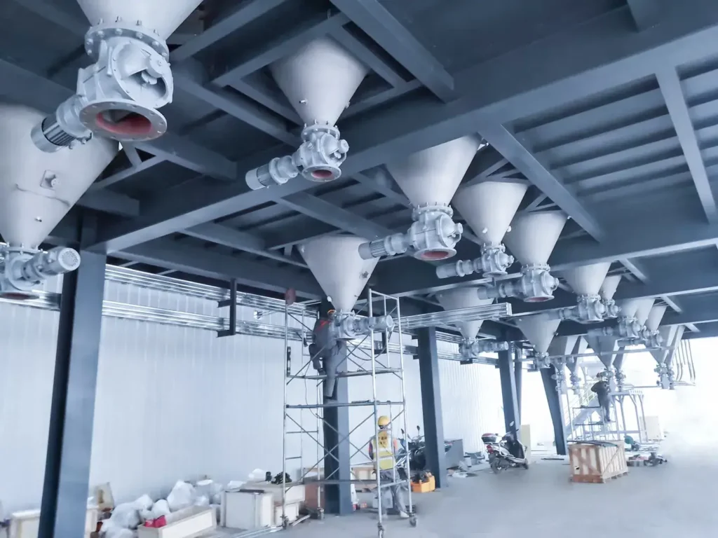
WIJAY Systems specifies and integrates rotary valves as part of fully engineered pneumatic conveying and bulk powder automation lines — not as a standalone commodity component. Because our systems are built around enclosed, dust-free conveying and automated, low-loss material handling across a wide range of industries, valve selection is treated with the same six-factor discipline outlined above: matched to product characteristics, differential pressure, temperature profile, and the regulatory or hygienic requirements of the specific plant. If your current rotary valve is generating recurring leakage, jamming, or wear complaints, that’s usually a selection issue, not an inherent limitation of the equipment — and it’s worth having engineers who see this failure pattern across many production lines review the specification before replacing the valve.