Table of Contents
If your finished parts are showing black specks, your conveying system is the first place to look — not the molding machine. Angel hair, streamers, and fines generated in pneumatic conveying lines are among the most common and least investigated sources of contamination in injection molding and compounding operations. This guide covers the engineering decisions that determine whether a plastic pellet conveying system runs cleanly.
Step 1: Use This Decision Framework Before Choosing Any Equipment
The single most common and costly mistake in plastic pellet conveying system design is selecting equipment before answering the fundamental engineering questions. Before you request a quote, run through this framework.
Plastic Pellet Conveying — System Type Decision Tree
| Plastic Pellet Conveying — System Type Decision | |
| Conveying distance < 100 m, multiple machines on one floor | Vacuum (dilute phase) |
| Conveying distance 100–400 m, single or multiple destinations | Vacuum dilute phase (preferred) or low-pressure positive |
| Conveying distance > 400 m (silo offloading, cross-building) | Positive pressure system |
| Glass fiber reinforced, abrasive, or long-fiber pellets | Dense phase or low-velocity dilute with ceramic bends |
| Soft resins (LDPE, TPU, flexible PVC) with angel hair history | Dense phase or VFD-controlled low-velocity vacuum |
| Hygroscopic resins (nylon, PET, PC, TPU), < 400 m | Vacuum + desiccant dryer integration at pump inlet |
| Hygroscopic resins, > 400 m or very high moisture sensitivity | Positive pressure with dry compressed air supply |
| Regrind with irregular geometry or variable bulk density | Vacuum dilute phase + agitator hoppers + oversized pickup tubes |
| ≤ 8 machines, flexible product mix, limited budget | Dedicated vacuum loaders per machine |
| ≥ 10 machines, multiple resins, long-term facility | Centralized pneumatic system with PLC sequencing |
Once you have identified which branch applies to your operation, the engineering work narrows considerably. The remaining sections go deeper on each decision point.
Positive Pressure vs. Vacuum: Which Architecture Fits Your Plant
Plastic pellets can be conveyed by both positive pressure and vacuum (negative pressure) systems — unlike many bulk materials that are locked into one approach. In positive pressure, compressed air at the start of the pipeline pushes material to its destination. In vacuum systems, a downstream pump creates lower pressure that draws pellets through the pipe. The right choice depends on your resin type, distance, and facility layout.
Beyond pressure mode, you also need to select the operating phase. Dilute phase keeps pellets suspended in the airstream at moderate velocity — lower cost, well-proven, suitable for most commodity resins at distances under 400 m. Dense phase moves material as slow plugs or slugs under higher pressure — the right choice when attrition, angel hair, or pipe wear is unacceptable with dilute phase. For most injection molding and extrusion applications, low-velocity dilute phase vacuum conveying is the engineering starting point.
| Parameter | Vacuum / Dilute Phase | Positive Pressure / Dilute | Dense Phase |
|---|---|---|---|
| Conveying distance | Up to 400 m | Up to 1,000 m | Up to 500 m |
| Pellet velocity | 180–240 m/min | 200–350 m/min | 60–120 m/min |
| Operating pressure | –20 to –60 kPa | 50–200 kPa | 100–600 kPa |
| Angel hair risk | Moderate — velocity-dependent | Higher at long distance | Very low |
| Equipment cost | Lowest | Medium | Highest |
| Best for | Machine-floor feeding, multi-machine plants | Silo/railcar offloading, long runs | GFR pellets, soft resins, medical/food-contact |
| Maintenance profile | Filter replacement, rotary valve seal wear | Compressor maintenance, pipe joint integrity | Pressure vessel inspection, valve wear |
Low-maintenance sourcing rule: The supplier who asks for your resin bulk density, pellet geometry, and conveying distance before quoting is protecting you from a system that will cause chronic maintenance issues. A supplier who quotes from catalog defaults is not.
The Angel Hair Problem: Deep Dive for Engineers
Angel hair — fine, fibrous polymer strands formed when pellets impact pipe walls at excessive velocity — is the most consequential and most misunderstood failure mode in plastic material handling. It is not a minor nuisance. Angel hair accumulates in bends and valve bodies, eventually breaking free into the melt stream, causing black specks, surface defects, and filter blockages in finished parts.
⚠ The Angel Hair Mechanism
When a pellet strikes a pipe bend at excessive velocity, the kinetic energy of impact generates localized frictional heat sufficient to soften the pellet surface. The material smears, stretches, and solidifies as a thin fiber attached to the pipe wall. Successive impacts build up layers. Eventually the fibers detach and enter the process stream. Softer resins (LDPE, TPU, flexible PVC, EVA) are most susceptible. Rigid materials (HDPE, PP, ABS) are affected at higher velocities. Even nylon and engineering resins produce angel hair when velocity control is poor. Glass fiber reinforced pellets produce a more aggressive variant — abrasive fiber fragments — with additional consequences for pipe wear and worker health.
The Three Engineering Fixes (All Three Required)
- ✓Velocity control: Target 180–240 m/min (600–800 ft/min) for commodity thermoplastics. LDPE and TPU: stay at 180 m/min. HDPE and ABS: up to 240 m/min acceptable. Above 280 m/min, angel hair is essentially guaranteed for most resins. Specify a VFD on the vacuum pump — it is the only way to dial velocity precisely per material type. Fixed-speed blowers cannot be properly tuned.
- ✓Long-radius bends: Standard 90° elbows create direct impact zones where pellets hit at full velocity. Long-radius sweeps (R/D ratio ≥10) spread the impact over a much larger surface area. Plug-tee (blind-tee) fittings cushion impact with a stagnant pellet plug in the dead leg — widely used in sensitive resin applications. Standard elbows are acceptable only for very short runs of rigid, non-sensitive resins.
- ✓Correct pipe bore: Undersized pipe increases velocity for a given mass flow — directly worsening angel hair and wear. Oversized pipe risks slug formation at low velocities. Pipe ID must be calculated from actual bulk density, pellet geometry, and target conveying rate — not estimated from a standard size catalog.
Dense Phase vs. Low-Velocity Dilute: When Each Is the Right Answer
Both approaches address angel hair, but through different mechanisms and at different cost levels. Understanding the boundary conditions prevents over-engineering — or under-engineering.
| Scenario | Low-Velocity Dilute Phase | Dense Phase |
|---|---|---|
| Commodity resins (PP, HDPE, ABS, nylon) | ✅ Sufficient with VFD + long-radius bends | ❌ Overengineered, cost not justified |
| Soft resins (LDPE, TPU, EVA) with angel hair history | ⚠️ Possible if velocity <180 m/min achievable | ✅ Recommended — eliminates root cause |
| Glass fiber reinforced pellets | ❌ Pipe wear too severe at any dilute-phase velocity | ✅ Required — or ceramic-lined dilute |
| Medical / food-contact parts (zero defect tolerance) | ⚠️ Requires extensive validation | ✅ Preferred for zero-compromise quality |
| Typical capital cost delta | Baseline | +40–80% over dilute phase system |
| Typical operating pressure | –20 to –60 kPa (vacuum) | 100–600 kPa (positive) |
| Pilot testing required? | No — well-characterized for common resins | Yes — flow behavior is material-specific |
Sizing a Plastic Pellet Conveying System
Sizing guides that list “consider bulk density and conveying distance” without showing the actual calculation leave engineers no better off. Here is a simplified but realistic sizing example for a dilute phase vacuum system — the most common configuration for injection molding plants.
Worked Example: PP Pellet Central Conveying System
1.Define the demand: 10 injection molding machines, peak simultaneous demand 5 machines, each consuming 250 kg/hr. Peak system throughput = 1,250 kg/hr. Design at 125% = 1,560 kg/hr design rate.
2. Material properties: PP pellets, bulk density 530 kg/m³, pellet diameter ~3 mm, non-hygroscopic, no angel hair history.
3. Target conveying velocity: 210 m/min (midpoint of 180–240 m/min range for PP). This gives ~3.5 m/s.
4. Pipe ID calculation: Using a solid-to-air ratio of ~8:1 (typical for dilute phase PP), air flow required ≈ 195 kg/hr = ~163 m³/hr at atmospheric conditions. Required pipe cross-section = Air flow ÷ velocity = (163/60) ÷ 3.5 = ~0.78 m² … at atmospheric → actual pipe ID = 75 mm nominal (standard 76.1 mm OD stainless). Verify: 163 m³/hr through 75mm ID at 3.5 m/s ✓
5. Equivalent pipe length: Actual pipe 85 m + 8 × 90° long-radius bends (each ≈ 5 m equivalent) + 2 diverter valves (each ≈ 10 m equivalent) = 145 m equivalent length.
6. Pressure drop estimate: For dilute phase PP at these conditions, total ΔP ≈ 25–35 kPa. Add pickup acceleration (≈ 10 kPa) and receiver filter (≈ 5 kPa) → ~45 kPa total. Specify vacuum pump for 55 kPa at design airflow (25% margin).
Preliminary specification: 75 mm nominal SS pipe, long-radius bends throughout, VFD-controlled vacuum pump rated 55 kPa / 165 m³/hr, PLC-sequenced receiver hoppers at each machine, desiccant filter on pump air inlet as precaution. This is a starting point — detailed engineering requires full pipe layout, actual bend count, and elevation changes.
Key sizing principle: Size for peak simultaneous demand, not average consumption. Undersized systems run at maximum velocity trying to catch up — exactly the condition that generates angel hair and pipe wear.
Pneumatic Conveying for Injection Molding Plants: System Architecture and Design Rules
Injection molding plants have a specific set of material handling requirements that general-purpose conveying guides routinely overlook. The demands here are different: multiple machines running simultaneously on different resins, shift-to-shift material changeovers, hygroscopic resins that degrade if exposed to ambient air during transfer, and the constant pressure to keep machine hoppers full without dedicating a worker to each one. Getting the conveying architecture right determines whether the system quietly supports production — or becomes the daily source of downtime calls.
The Core Architecture Decision: Dedicated Loaders vs. Centralized System
Before specifying any hardware, the first decision is architecture. It sets everything else.
Dedicated vacuum loaders (one loader per machine, each pulling from a nearby Gaylord or bin) are the right starting point for small operations: under 8 machines, limited resin variety, low capital budget. Setup is fast, the system is easy to understand, and failures are localized — one loader goes down, one machine is affected. The trade-off is labor: someone has to monitor and replenish each source container, and material traceability across the floor is manual.
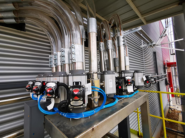
Centralized pneumatic conveying is the correct architecture for injection molding plants running 10 or more machines, multiple resin types, or any facility where labor cost and production consistency matter. One central vacuum system — typically a roots blower or liquid ring pump — serves all machine points through a manifold of conveying lines and diverter valves. Material moves from centralized silos or bulk storage through sealed stainless steel piping directly to each machine hopper receiver. PLC sequencing manages which machine gets material and when, based on hopper level sensors at each receiver.
The switchover point is typically 8–10 machines. Below that, dedicated loaders are simpler and cheaper to run. At 10 machines and above, the labor savings and consistency gains from centralization typically pay back the installation cost within 12–24 months.
How a Centralized Injection Molding Conveying System Is Laid Out
A well-designed centralized system for an injection molding plant has five physical zones:
Zone 1 — Bulk Storage. Silos (for truckload or railcar resins) or bag dump stations with hopper (for 25kg or 1,000kg bags). This is where material enters the system. For hygroscopic resins — nylon, PET, PC, ABS — pre-drying at this stage or at Zone 2 is mandatory.
Zone 2 — Drying. Centralized desiccant drying hoppers, sized to maintain a minimum residence time for each resin (typically 4–6 hours for nylon and PET at the correct temperature). Drying is integrated into the conveying circuit, not bolted on as an afterthought. Resins that skip proper drying produce splay marks, silver streaks, and reduced mechanical properties in finished parts — regardless of how well the conveying system performs downstream.
Zone 3 — Distribution Manifold. A diverter valve network that routes material from any source to any machine destination. In a plant running 6 resins to 20 machines, this is the control heart of the system. PLC-managed valve sequencing prevents cross-contamination between materials and enforces proper purge sequences between changeovers.
Zone 4 — Conveying Lines. Stainless steel tubing running through cable trays or overhead racks to each machine point. Line sizing follows the same velocity and pipe bore principles described in the Sizing section above — but in injection molding plants, lines often run vertically (up through mezzanine floors to overhead routing, then down to machine throats), which adds elevation pressure drop to the design calculation.
Zone 5 — Machine Receivers. A receiver hopper at each machine with a level sensor, a filter, and a timed fill cycle controlled by the central PLC. When the hopper drops below the set level, the PLC opens the correct diverter valve, runs the vacuum pump for a preset cycle, and shuts off — the hopper refills without any operator involvement. Filter maintenance at the receiver is the primary routine maintenance task in a well-designed system.
Design Rules Specific to Injection Molding Applications
These rules go beyond general conveying guidelines and apply specifically to the injection molding production environment:
Rule 1: Size for peak simultaneous demand across all machines, not average consumption.
If 20 machines are running, not all 20 call for material at the same second — but during a busy shift, 8–12 may call within the same 5-minute window. Design the central pump capacity and pipe network for the realistic peak simultaneous demand, not the average. A system that can’t keep up at peak forces machines to run with low hoppers, which destabilizes feed consistency.
Rule 2: Run separate conveying lines for incompatible resins.
Sharing a single trunk line between chemically incompatible resins (for example, PVC and acetal, or nylon and LDPE) requires very thorough purging between changeovers and still carries contamination risk. In plants with resins that absolutely cannot cross-contaminate — medical-grade parts, food-contact applications, or color-critical jobs — dedicated lines per material family are worth the additional pipe cost. In standard commercial molding operations, one shared trunk with rigorous PLC-enforced purge sequences is the normal approach.
Rule 3: Match the drying architecture to the resin sensitivity, not to one-size-fits-all.
Non-hygroscopic resins (PP, HDPE, ABS in non-critical applications) can often be conveyed directly from storage without drying. Hygroscopic resins (nylon PA6/PA66, PET, PC, TPU, POM) require drying to a specific moisture level before processing — the dew point at the conveying air inlet must be below -20°C for the most sensitive resins. Integrating drying into the conveying design from the start — rather than retrofitting dryers later — is always less expensive and more reliable.
Rule 4: Install a VFD on the central vacuum pump, not a fixed-speed motor.
Injection molding plants frequently switch resins — sometimes multiple times per shift. Each resin has a different optimal conveying velocity. A fixed-speed pump runs at whatever velocity it produces regardless of material, which means some resins run too fast (angel hair risk) and others too slow (plugging risk). A VFD-controlled pump allows the operator or PLC to dial velocity per material type. For a plant running soft resins like LDPE or TPU alongside rigid resins like HDPE or ABS, the VFD is not optional — it is what allows the same system to handle both without chronic problems.
Rule 5: Map the complete purge sequence before commissioning.
Every centralized system needs a documented purge protocol: how many seconds of clean-air purge to run after each material conveying cycle, and how many full-line purge cycles are required at material changeover. The purge time depends on line length, pipe volume, and the contamination tolerance of the next material going through the line. Skipping this step during commissioning is the single most common cause of cross-contamination complaints in shared-line systems at injection molding plants.
What This Looks Like at Scale: 46-Machine Injection Molding / Extrusion Facility
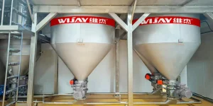
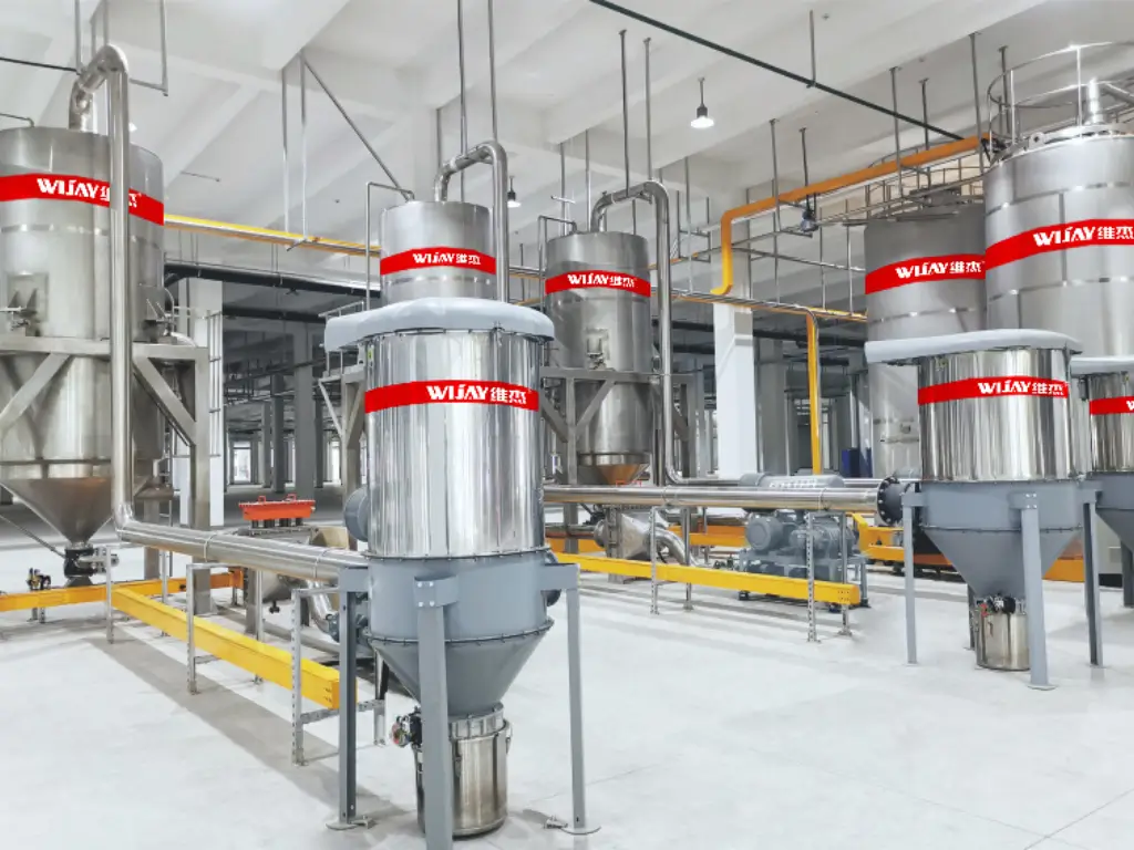
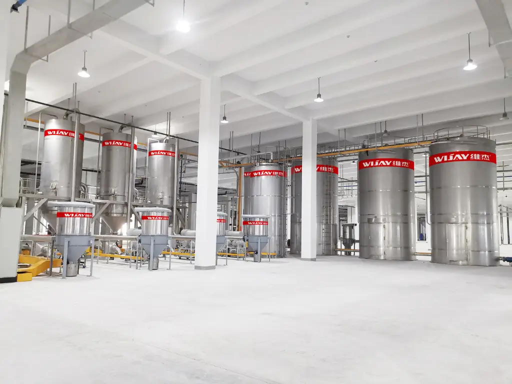
A centralized system WIJAY designed for a plastic formwork manufacturing base illustrates how these principles scale. The facility runs 46 large-scale sheet extruders on 6 distinct materials — base resins plus additives — at a total feed rate of 36 t/hr across conveying distances up to 200 meters.
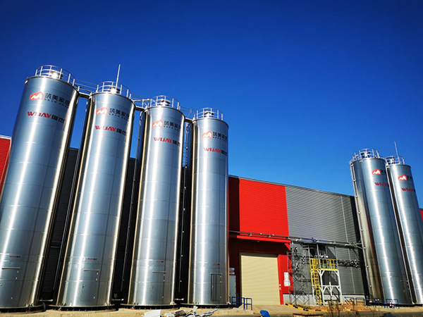
Individual machine-side feeders and dryers at this scale would have required 46 separate units, 46 maintenance schedules, and a team of operators monitoring material levels across the floor. Instead, the centralized positive pressure system connects 6 silos, 6 drying systems, and 46 machine points through a single automated valve manifold. Any of the 6 materials can be routed to any of the 46 machines without operator intervention — the central information control system handles sequencing, logs material consumption per machine, and provides real-time inventory data to management via office workstations or mobile devices.
Total material storage capacity in the system: 1,200 tonnes. Operator involvement for routine material feeding: near zero.
Have a similar multi-machine injection molding layout? [Request a technical layout review →]
Troubleshooting: When Your Plastic Conveying System Is Already Running
A significant proportion of engineers searching for pneumatic conveying system recommendations for pellet handling are not designing new systems — they are diagnosing problems with existing ones. This section addresses the most common failures and their root causes.
| Symptom | Most Likely Cause(s) | First Diagnostic Step |
|---|---|---|
| Pipeline blockage / plugging | Velocity below minimum conveying threshold; moisture-bridged material at pickup; undersized pipe for density of current resin batch | Check vacuum gauge reading vs. design spec. Drop in vacuum = blockage downstream. Measure actual bulk density of current batch vs. design value. |
| Angel hair increasing suddenly | VFD setpoint drifted or overridden; switch to higher-density resin without velocity adjustment; elbow or bend replaced with standard 90° fitting | Verify VFD output frequency and actual measured velocity. Inspect all bends — confirm long-radius or plug-tee fittings are in place and not worn through. |
| Inconsistent feed rate to machine | Receiver hopper filter blinding (back-pressure reduces throughput); leaking rotary valve; sequencing logic errors in PLC with multiple machines competing | Check receiver filter differential pressure. Clean or replace filter bags. Verify rotary valve shaft seal condition. Review PLC cycle logs for sequencing conflicts. |
| Black specks in finished parts | Angel hair accumulation detaching from bends or valve internals; degraded material from dead zones in poorly designed hopper geometry | Disassemble and inspect all bends — black/brown fibrous deposits confirm angel hair. Check hopper geometry for stagnant zones where material can overheat. |
| Excessive pipe wear at bends | Abrasive resin (GFR, mineral-filled) running in standard steel dilute-phase system; velocity too high for material hardness | Measure remaining wall thickness at outside radius of bends using ultrasonic gauge. If <2 mm, replace immediately. Consider ceramic-lined bends or dense phase conversion. |
| Moisture in resin at machine hopper | Vacuum pump drawing ambient humid air; desiccant dryer bypassed or exhausted; conveying pipe leaks allowing moisture ingress | Check desiccant dryer dew point. Inspect all pipe joints for air leaks (soap test or pressure decay test). Verify dryer regeneration cycle is functioning. |
Real Project Cases: What These Systems Look Like at Scale
Engineering decisions make more sense with real numbers behind them. The following projects illustrate how the design principles above translate into operating systems.
PLASTICS · EXTRUSIONPlastic Formwork Manufacturing Base — Centralized Multi-Material Feeding
36 t/hrTotal feed rate
200 mMax conveying distance
46Sheet extruders served
Six distinct materials — base resins plus additives — continuously supplied to 46 large-scale sheet extruders. The challenge: a traditional setup of individual vacuum feeders and small dryers could not maintain consistent temperature and humidity control at this throughput and could not scale to 46 simultaneous machine points. Wijay designed a centralized positive pressure intermediate phase system with an automated valve manifold connecting 6 silos, 6 drying systems, and 46 material points.
The central information control system provides real-time inventory and consumption data across all production lines. Management monitors via office workstations or mobile devices. Material storage capacity: 1,200 tons. The system enabled flexible production — any of the 6 materials routed to any of the 46 machines — without operator intervention.View full case study →
CABLE MATERIALS · ULTRA-LONG DISTANCE Futong Group Cable Manufacturing Base
60 t/hrProcessing capacity
>600 mMax conveying distance
180Production lines served
Nine types of powdered and granular raw materials plus two types of paste materials, supplying 180 production lines at annual capacity of 90 million core kilometers. At 600 m conveying distance, positive pressure conveying is the only viable mode — vacuum systems are limited to ~400 m. Wijay’s patented technology addressed ultra-long-distance conveying, wire drawing risk, dust control, and online metal removal simultaneously.
The system’s software integrates directly with the factory MES and enterprise ERP — all material information and usage data measured and recorded. Online moisture content measurement and control improved product yield rates and established a new technical benchmark for the cable materials industry.View full case study →
What to Ask When Evaluating Plastic Pellet Conveying System Manufacturers
Not all plastic material handling equipment suppliers approach engineering with the same rigour. These questions separate capable system suppliers from catalog vendors:
- ✓Material-specific sizing: Does the supplier request your actual resin bulk density and pellet geometry, or size from a catalog default? If they have not asked, they are not sizing for your system.
- ✓Angel hair data: Can they provide angel hair test results for your specific resin at the proposed conveying velocity? For sensitive resins, this should be a deliverable, not a promise.
- ✓Pipe and bend specification: Do they specify pipe material, wall thickness, and bend type — or leave these to the installation contractor? Every design decision about bends and pipe material was made by someone; ensure it was a qualified engineer.
- ✓Control system detail: Is the PLC brand, I/O count, and MES connectivity documented in the proposal, or described vaguely as “fully automated”? Vague control specifications become expensive change orders.
- ✓References at scale: Can they provide references from facilities running the same resin type at comparable throughput and distance? Pilot installations are not equivalent references for production-scale systems.
- ✓TCO data: Can they provide typical energy consumption (kWh/tonne conveyed), filter replacement intervals, and rotary valve overhaul schedules? These numbers determine whether a lower-cost system is actually cheaper over its operating life.
Frequently Asked Questions
What is the correct conveying velocity for plastic pellets, and where does that number come from?
The 180–240 m/min (600–800 ft/min) range is derived from the balance between two failure modes: below ~150 m/min, dilute phase suspension breaks down and slugging occurs; above ~280 m/min, frictional heat at bends exceeds the softening point of most thermoplastics. The exact threshold varies by resin — LDPE softens at lower temperatures than HDPE. VFD-controlled systems can be tuned to the precise minimum for each resin. Fixed-speed systems run at whatever velocity the motor produces, regardless of whether it is optimal.
When should I use dense phase instead of dilute phase for plastic pellets?
Dense phase is warranted when: (1) the material is glass fiber reinforced or otherwise abrasive — dilute phase causes pipe erosion at any practical velocity; (2) you have a soft resin with persistent angel hair that low-velocity dilute phase has not resolved; (3) parts are food-contact or medical-grade with zero defect tolerance; or (4) pellets are genuinely fragile and generate fines in dilute phase. For most commodity resin applications, low-velocity dilute phase vacuum conveying is sufficient and significantly less expensive to install and maintain.
What maintenance does a centralized plastic pellet conveying system require?
Primary maintenance items: receiver filter bag replacement (typically every 3–12 months depending on material dustiness and batch frequency); rotary valve tip seal replacement (typically 6,000–10,000 operating hours); vacuum pump oil or bearing service per manufacturer schedule; and periodic pipe wall thickness checks at bends for abrasive resins. A properly designed system running commodity resins requires very little unplanned maintenance — most failures trace to incorrect velocity setting, filter neglect, or substandard bend specification at installation.
Can one pipeline convey multiple resin types?
Yes — with appropriate design. Centralized systems with diverter valve manifolds routinely switch between resin types. Key requirements: adequate purging sequence between materials (typically 1–3 minutes of clean air flush), compatible velocity settings for all resins in the system (the lowest acceptable velocity for the most sensitive resin sets the system baseline), and a control system that enforces proper sequencing. Cross-contamination is a real risk if purge sequences are skipped or improperly timed.
How much does a plastic pellet conveying system cost?
Dedicated vacuum loaders for a single machine: $2,000–$8,000 per machine point depending on throughput and dryer integration. Centralized dilute phase vacuum system for 10–20 machines: $80,000–$300,000+ depending on distance, number of material sources, pipe routing complexity, and control system specification. Dense phase or highly automated systems with MES integration scale higher. Energy consumption for dilute phase vacuum systems is typically 1.5–4 kWh per tonne of material conveyed, depending on distance and bulk density.
Where to Source Low-Maintenance Pneumatic Conveying Systems for Plastic Pellets
Source from a supplier who sizes the system from your actual resin data — bulk density, pellet geometry, and conveying distance — before quoting. If they didn’t ask for these, the system wasn’t sized for your operation. WIJAY has supplied dilute phase vacuum conveying systems for plastic pellet handling across injection molding, extrusion, and compounding plants. Our systems handle up to 30 t/hr at conveying distances up to 300 meters, operating at –10 psig (~–69 kPa) vacuum, with dust collection efficiency of 99.99% and dosing accuracy of ±2‰ (weighted integration).