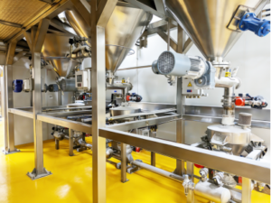
Most powder and granulate processing plants don’t set out to build an unreliable material handling setup. It happens gradually — a feeder gets added to solve one workstation’s problem, then a blower for another, then a dust collector bolted on wherever there’s floor space, each purchase justified on its own as the fast, low-budget way to get that one line running. A few expansion cycles later, the plant has a facility full of standalone equipment from different vendors, different eras, and different specs, none of it designed to work together.
The bill for that approach doesn’t show up on the purchase order — it shows up in the daily unclog cycle nobody remembers scheduling, the dust levels that keep drifting past acceptable limits, the cross-contamination between material runs, and the day someone finally asks why adding one new production line means ripping out half the existing piping. As capacity pressure, quality standards, and environmental compliance requirements all tighten industry-wide, a facility built from scattered single-unit equipment is running out of room to keep up.
This guide breaks down why piecemeal conveying setups fail predictably at scale, and what actually goes into planning a plant-wide pneumatic conveying system that holds up under continuous, multi-line production — not just the sales pitch version, but the specific planning elements that determine whether the system performs.
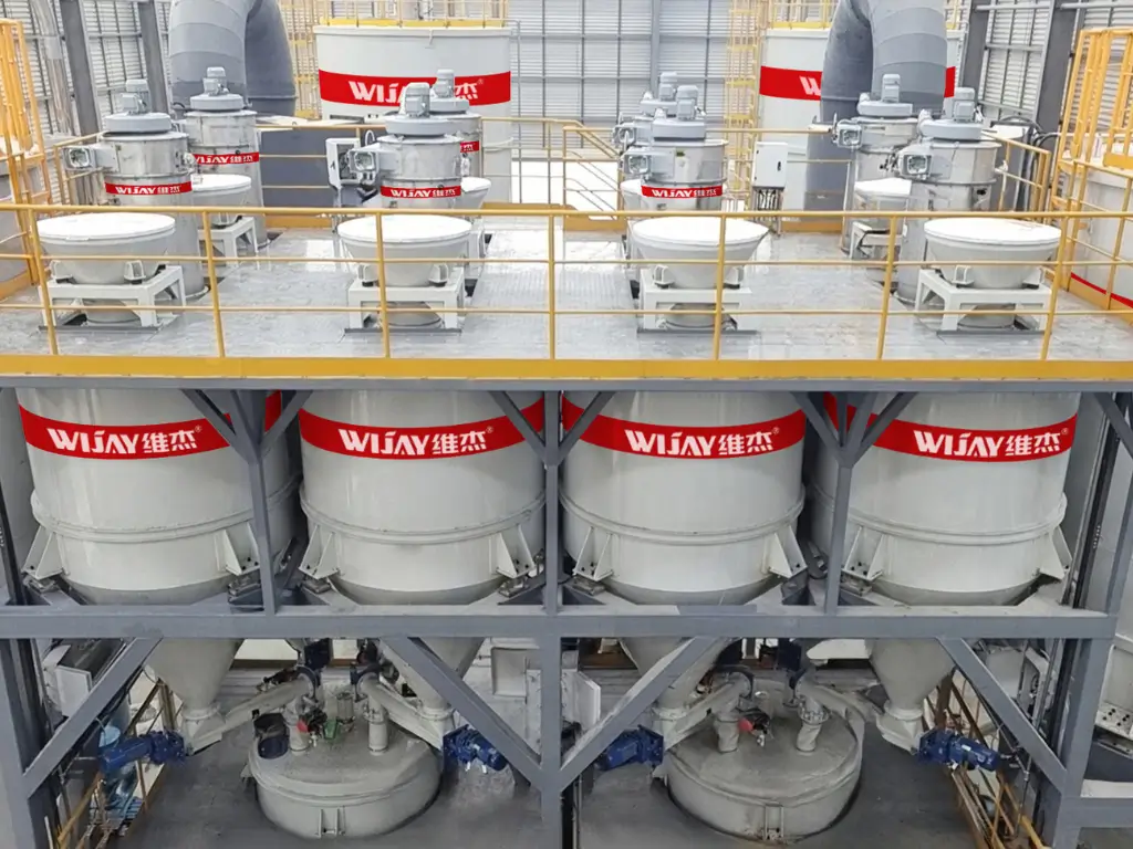
Background: The Real Cost of Building a Conveying System One Unit at a Time
Why “Fast and Cheap” Standalone Equipment Gets Expensive Over Time
Assembling a facility’s material handling capability from individually purchased feeders, blowers, storage units, and dust collectors — each sized and specified for its own workstation in isolation — creates four compounding problems as the plant scales.
Equipment incompatibility drives chronic instability. Different brands and models carry different air pressure ratings, flow ratios, pipe diameters, and control logic. Stitched together on-site without unified engineering, the combined system runs with unbalanced pressure and inconsistent velocity, which shows up as material buildup, localized blockages, and starved end points. Plants running this way commonly report multiple unclog stoppages per day, each one breaking production rhythm and capping how much of rated capacity actually gets realized.
Redundant equipment and disorganized piping create a management burden. Each workstation with its own hopper, blower, piping run, and dust collector means duplicated equipment spread across the floor and pipe runs crossing wherever they happen to fit. Beyond the wasted floor space and safety hazard of cluttered routing, scattered equipment locations and disorganized piping multiply the time needed for daily inspection, fault diagnosis, and routine maintenance — and make a genuinely standardized, clean facility layout difficult to achieve.
Contamination and material loss climb, and product consistency suffers. Standalone units are typically simple in construction — no proper screening, no enclosed dust control, no self-cleaning structure. Airborne dust during transfer lets exposed powder absorb moisture and pick up contamination. When multiple materials run through the same disconnected equipment, residue from standalone units can’t be fully cleared between changeovers, which shows up downstream as cross-contamination, inconsistent finished product quality, and material loss that quietly inflates production cost.
There’s no room to expand, and retrofitting later is expensive. A piecemeal build is inherently a fixed, one-off layout with no reserved interface for future capacity or new production lines. When the plant needs to expand or add a new material or workstation, the existing equipment and piping typically can’t adapt — forcing large-scale demolition and rebuild, which wastes the original equipment investment and adds significant retrofit cost and downtime on top of it.
Core Technical Explanation: What a Plant-Wide Integrated System Actually Requires
A plant-wide material automation system isn’t simply “more equipment installed at once” — it’s systems engineering, requiring design work matched to facility conditions, material properties, and production targets rather than a generic equipment package applied without adaptation.
Full-Dimension Site Survey as the Planning Foundation
Before any equipment is specified, a complete facility survey needs to establish: room dimensions, column and beam layout, existing equipment placement, conveying distances, and floor-to-floor elevation changes, combined with a full material inventory covering physical/chemical properties, hourly throughput, shift patterns, and changeover frequency — plus the facility’s required cleanliness classification, explosion-proof rating, and environmental compliance standards. This data becomes the baseline the rest of the design is built against, rather than defaulting to a generic system based on experience alone.
Conveying Process Simulation to Prevent Blockage Before It Happens
Using the material’s density, flowability, moisture sensitivity, abrasiveness, and static behavior, simulation work calculates the optimal conveying velocity, pressure ratio, pipe diameter, elbow count, and routing layout for the specific application — flagging blockage and buildup risk on long runs, multi-turn routing, and high-frequency changeover conditions before fabrication, not after installation.
Modular Design Matched to Industry-Specific Requirements
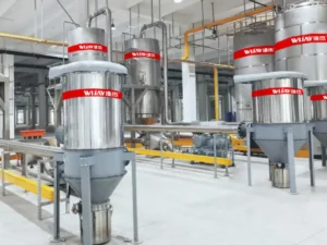
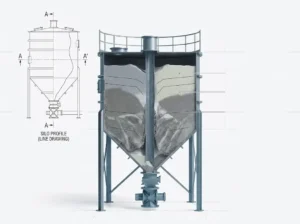
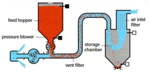
A plant-wide system should be built from selectable functional modules — enclosed feeding, screening/impurity removal, pneumatic conveying (vacuum/negative-pressure or positive-pressure), intelligent storage, dust collection/recovery, automated self-cleaning purge, explosion-proof/anti-static protection, and central control — configured to the actual industry application rather than applied as a single fixed package.
| Industry | Typical Modular Emphasis |
|---|---|
| Food & beverage | Food-grade stainless steel, polished surfaces, CIP-compatible enclosed feeding and screening for sanitary compliance |
| Lithium battery / fine chemical | Full explosion-proof and anti-static component sets for high-risk dust conditions |
| General chemical/plastics | Wear- and corrosion-resistant piping for abrasive or reactive material handling |
Unified Plant-Wide Piping Layout
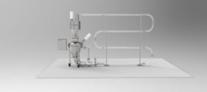
Rather than scattered, ad-hoc routing, a plant-wide design plans main lines, branch lines, and sub-routes as one coordinated network — routed around columns, existing equipment, and traffic paths, with unnecessary elbows and redundant runs eliminated. A clean, organized piping layout preserves usable floor space, reduces maintenance blind spots, and supports the standardized, visually manageable floor plan modern facilities are increasingly expected to maintain.
Central Intelligent Control for Full-Process Coordination
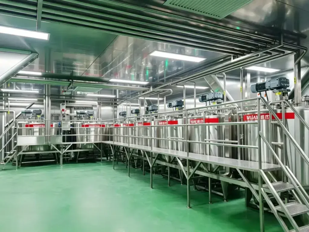
A unified control layer monitors every conveying, dust collection, and storage unit from one system, tracking pressure, flow, material level, and temperature in real time. This is what allows the system to adjust conveying parameters dynamically as throughput changes, balancing supply across multiple workstations and eliminating the material contention, starvation, and uneven supply that standalone units can’t coordinate against each other.
Built-In Expansion Capacity
A properly planned system uses a modular, expandable architecture with reserved interfaces on piping, electrical control, and power units. When the plant later adds a production line, workstation, or material type, the expansion connects into the existing system rather than requiring a full teardown and rebuild — protecting the original capital investment against the plant’s future growth plans.
AGV Integration for Finished and Semi-Finished Material Flow
Beyond raw material conveying, an Automated Guided Vehicle (AGV) layer can move finished and semi-finished goods between process stages and between production and warehouse areas without manual handling, connecting directly with the pneumatic conveying system to close the loop from raw material intake through to finished goods storage.
Practical Field Troubleshooting & Decision-Making Guidance
Is Your Current Setup a Piecemeal Build That’s Outgrown Itself?
| Symptom | Standalone-Equipment Root Cause | Adjustable Fix | Sign You Need a System-Level Redesign |
|---|---|---|---|
| Multiple unclog stoppages per day | Mismatched pressure/flow between independently sourced units | Recalibrate individual unit settings | Stoppages persist across multiple units regardless of tuning — pressure/flow was never balanced at a system level |
| Chronic dust complaints in specific zones | Standalone units lack enclosed dust control | Add local containment | Dust issues are facility-wide and tied to multiple uncoordinated feed points |
| Cross-batch contamination on changeover | No self-cleaning structure on individual units | Manual cleaning between runs | Contamination recurs structurally because no unit has purge capability designed in |
| New line or workstation can’t be added without major rework | No reserved capacity or interface in the original piecemeal layout | This is a structural limitation | Confirms the system needs to move to a modular, expansion-ready architecture |
| Frequent, hard-to-diagnose faults across scattered equipment | No central monitoring — faults are found manually, after the fact | Increase inspection frequency | Fault detection time isn’t improving because there’s no unified control layer to flag issues in real time |
Rule of thumb: if tuning individual units keeps producing short-term relief, but the same failures recur across different equipment, the root cause is structural — the system was never engineered as one coordinated design, and no amount of per-unit adjustment fixes that.
Key Design & Operation Best Practices
- Treat the site survey and material data as the design foundation, not a formality — a system specified without it defaults to generic assumptions that don’t hold up in your actual facility.
- Run conveying simulation before finalizing piping, especially on long runs, multiple turns, or frequent changeover conditions — this is where blockage risk gets caught on paper instead of on the production floor.
- Match module selection to your specific industry compliance requirements, not a one-size-fits-all package — food, battery-material, and chemical applications each carry a different risk profile.
- Plan piping as one coordinated network from the start, not zone-by-zone — this is what prevents the clutter and maintenance blind spots that piecemeal builds accumulate over time.
- Build in expansion capacity even if you don’t need it yet — reserved interfaces on piping and control cost far less to include upfront than to retrofit after the plant has already outgrown a fixed layout.
- Weight central control as core scope, not an add-on — coordinated, real-time monitoring is what actually prevents the material contention and starvation that independent units can’t resolve on their own.
Common Mistakes & Pitfalls to Avoid
- Assuming individually purchased “off-the-shelf” units will work together as a system. Different pressure ratings, flow logic, and pipe specs from different sources rarely balance correctly once installed together.
- Optimizing each new equipment purchase for the lowest unit price without a plant-wide plan. This is exactly how a facility ends up with duplicated hardware and no coordinated layout a few expansion cycles later.
- Underestimating the cost of not having reserved expansion capacity. A piecemeal layout with no interface for growth turns a routine capacity expansion into a large-scale, expensive rebuild.
- Applying a generic conveying package across different materials without industry-specific modular design. Sanitary, explosion-proof, and wear-resistance requirements differ enough between food, battery-material, and chemical applications that a single template doesn’t fit all three.
- Skipping simulation on long-distance or multi-turn routing. This is one of the most common and most avoidable causes of chronic post-installation blockage.
- Treating central control as optional. Without it, a plant-wide system still behaves like a collection of independent units when it comes to fault detection and load balancing — undermining the core value of integrating them in the first place.
FAQ
What’s the main disadvantage of using standalone conveying equipment instead of a plant-wide system?
Standalone units purchased and installed independently typically carry mismatched pressure and flow specifications, which shows up as chronic blockage, uneven supply, and cross-contamination once the plant is running multiple lines — problems a unified, engineered system is specifically designed to avoid.
How much more does a plant-wide pneumatic conveying system cost compared to piecemeal equipment?
It depends heavily on facility size, material complexity, and compliance requirements, so there’s no universal figure — but piecemeal builds often carry hidden costs in duplicated equipment, higher material loss, and expensive future retrofits that don’t show up in the initial purchase price comparison.
Can an existing facility with standalone equipment be converted into a plant-wide integrated system?
In many cases, yes—a site survey can identify which existing equipment is compatible with an integrated redesign and which needs replacement, but this depends on the current layout and equipment condition and warrants a dedicated assessment rather than a generic answer.
Does a plant-wide conveying system use vacuum (negative-pressure) or positive-pressure conveying?
Either can apply, depending on material properties, distance, and layout—the choice should be based on simulation for your specific application rather than a default assumption.
How does AGV integration work with a pneumatic conveying system?
Pneumatic conveying handles raw material transfer through enclosed piping, while an AGV layer moves finished and semi-finished goods between process stages and storage areas — when integrated, the two together can close the material flow loop from raw material intake to finished goods storage without manual handling in between.
Ready to Plan a Plant-Wide Conveying System for Your Facility?
Every facility’s layout, material mix, and growth plans are different, which is why a copy-paste equipment package tends to underperform at scale. Share your material list, hourly capacity targets, facility layout, and site distance so an engineering team can assess your specific conveying requirements and propose a modular, expansion-ready system design before equipment is specified.