Energy-efficient pneumatic conveying system design isn’t a single feature you add to a system — it’s the sum of a handful of specific engineering decisions, and skipping any one of them tends to erase the benefit of getting the others right. Pneumatic conveying is already one of the cleanest, most reliable ways to move dry bulk materials through a plant, using compressed air or an inert gas to carry powders, pellets, or granules through enclosed pipelines with minimal contamination risk or product damage. But “pneumatic conveying” as a category covers systems with wildly different energy profiles, and the difference between an efficient one and a wasteful one usually comes down to a handful of decisions made — or skipped — at the design stage.
This article breaks down how pneumatic conveying actually works, what genuinely drives energy efficiency, and a real case where a system had been running on roughly double the compressed air it actually needed for months before anyone caught it.
How Pneumatic Conveying Actually Works
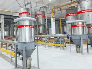
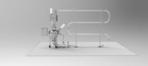
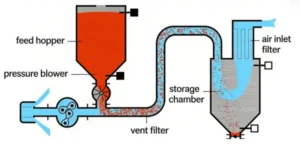
At its core, pneumatic conveying uses compressed gas to move bulk material through a closed pipeline, and the system breaks down into a few key components. A compressed gas source — air or an inert gas like nitrogen — provides the power, either pushing or pulling material through the line. Material enters the system at a feed point, typically through a feeder, rotary valve, or pressure vessel. It travels through a pipeline sized for the material’s specific velocity and wear requirements. And it’s collected at a receiver or separator, where the conveying gas vents while the material is captured.
The system can be configured as positive pressure, where gas pushes material from one point to another — generally the better fit for longer distances or higher throughput — or negative pressure (vacuum), where a vacuum pulls material through the line, which tends to suit shorter distances and multiple pickup points feeding a single destination.
Dilute Phase vs. Dense Phase: Why the Choice Affects Energy Use Directly
Dilute phase conveying suspends material in a fast-moving gas stream, typically at velocities of 5,000 to 9,000 feet per minute. It works well for light, non-abrasive, non-fragile materials — clay, flour, plastic pellets are common examples — and it generally costs less to install with more routing flexibility. It’s best suited to non-fragile materials over shorter distances.
Dense phase conveying moves material at a much lower velocity, typically 400 to 2,000 feet per minute, in a compact slug or plug flow rather than fully suspended in the airstream. This is the better fit for fragile, abrasive, heavy, or moisture-sensitive materials — cement, catalysts, and powdered chemicals are common examples — and it delivers minimal product degradation, reduced pipeline wear, a more controlled process environment, and meaningfully lower energy use. It’s generally the right choice for long distances, high transfer rates, and difficult materials.
The energy difference between the two isn’t incidental — dense phase is inherently more efficient because it moves material at lower velocity and requires substantially less air volume to do it. But that efficiency only shows up if the dense-phase system is actually calibrated correctly; simply choosing “dense phase” as a category doesn’t guarantee the energy savings if velocity and air volume aren’t properly matched to the material.
What Actually Makes a System Energy-Efficient
Energy efficiency isn’t a property a system has by default — it’s engineered in through several specific decisions working together.
Optimized air velocity. The right speed keeps material moving without excessive pressure loss, and the relationship is intuitive once you think about it the right way: an Indy car burns far more fuel per mile than a compact car, and wears through a set of tires far faster too. A conveying system running faster than it needs to isn’t just wasting compressed air — it’s accelerating equipment wear at the same time, which means the energy cost and the maintenance cost of an oversized velocity compound rather than staying separate problems.
Accurate line sizing. Pipe diameter determines the actual velocity achieved at a given material rate, and a line sized even modestly wrong — too small or too large for the actual throughput — forces the system to compensate with more air pressure than the material transfer genuinely requires.
Low-leak components. Valves, couplings, and diverters that aren’t properly engineered or properly matched to the system introduce leak paths that waste compressed air continuously, not just occasionally — a small, chronic leak across a system’s operating life adds up to a meaningful energy cost that’s easy to overlook because it never shows up as a single dramatic failure.
Demand-driven gas delivery. A well-designed system adjusts the compressed gas volume to the rate actually being run, rather than delivering a fixed volume regardless of throughput. A system designed for 20 tons per hour that’s actually running at 10 tons per hour should use roughly half the compressed air of full-rate operation — but only if the system is engineered to adjust automatically rather than running at a fixed setting regardless of demand.
Properly calibrated dense-phase systems, combining all of these factors, can reduce energy consumption significantly compared to conventional dilute-phase or poorly calibrated dense-phase alternatives — but the reduction comes from the combination of these specific engineering choices, not from the phase classification alone.
A Case Worth Sharing: The System Running on Double the Air It Needed
We worked with a plant running a dense-phase conveying system that had been installed with a fixed compressed air delivery rate, sized for the plant’s peak production rate. The system worked reliably — throughput was consistent, product degradation was low — which is exactly why nobody had flagged it as a problem for months.
The issue only surfaced during a broader energy audit: the plant was frequently running at roughly half its rated throughput during a significant portion of normal operation, but the conveying system was still delivering compressed air at the volume calibrated for full-rate production, regardless of actual demand. The system wasn’t malfunctioning — it simply hadn’t been engineered to adjust gas delivery to actual throughput, so it was burning close to double the compressed air genuinely required during those lower-throughput periods. Retrofitting the system with demand-driven gas delivery, so air volume scaled with actual rate rather than running at a fixed setting, cut compressed air consumption meaningfully during normal operation without any change to throughput or product quality. The lesson: a system can run reliably for months, hit every performance target that gets checked, and still be quietly wasting a substantial amount of energy — because reliability and efficiency aren’t the same measurement, and only one of them gets checked by default in most routine operations.
Custom System Design: Why “One-Size-Fits-All” Doesn’t Apply Here
Every material behaves differently under conveying conditions, which is why genuinely effective system design starts with understanding the specific material and the specific process before anything gets specified — not the other way around. A conveying system designed from a generic template, then adjusted to accommodate a particular material after the fact, tends to underperform on efficiency even when it technically meets throughput requirements, because the velocity, line sizing, and gas delivery were never actually calibrated to that material’s real behavior.
The disciplined approach that actually delivers energy-efficient design starts with material testing under real conveying conditions, moves through system modeling to validate the design before fabrication, proceeds to precision component fabrication built to that specific design, and finishes with installation and commissioning that verifies the system performs as modeled — not just as specified on paper.
What to Expect on Project Timelines
Project timelines vary considerably depending on system complexity. A standard dilute-phase system typically runs 2–3 weeks of design time and 6–8 weeks of fabrication, for a total estimate around 8–10 weeks. A custom dense-phase system generally needs 4–6 weeks of design and 10–14 weeks of fabrication, totaling roughly 14–20 weeks. A full turnkey system — design, fabrication, and integration with existing plant infrastructure — typically runs 6–8 weeks of design and 12–16 weeks of fabrication, for a total around 18–24 weeks. These are general ranges; actual timelines depend on project scope, material availability, and how much of the system needs to integrate with existing equipment.
Common Issues That Undermine Efficiency Over Time
Even a well-designed system can develop efficiency problems over its operating life, and most trace back to a handful of recognizable causes.
Reduced transfer rate typically has one of three causes: the material itself has changed — particle size, moisture content, or bulk density drifted from what the system was originally calibrated for; the system’s operating parameters have drifted out of their original adjustment; or the compressed gas supply itself isn’t delivering clean, dry air at the correct pressure anymore.
Material buildup on internal equipment surfaces most commonly appears downstream of a material dryer, caused by saturated air between particles condensing on cooler equipment surfaces further down the line. The fix is typically a cooling stage after the dryer that purges that saturated air from the material before it reaches downstream equipment.
Excessive wear usually results from conveying abrasive material at velocities higher than the material can tolerate. Switching to dense-phase conveying reduces this substantially, but if a dense-phase system is still showing high wear, it’s usually a sign the system has drifted out of its original calibration or is running at a rate meaningfully above its design capacity.
Pressure drops are frequently traced to non-original components — couplings, bends, diverters, or valves substituted in during maintenance that don’t match the system’s original engineering — introducing resistance or leak paths the original design didn’t account for.
Why the Purchase Price Is the Smaller Number
A conveying system gets purchased and installed once, then operated for years — and over that operating life, energy and maintenance costs dwarf the initial equipment cost. That’s the practical argument for treating energy-efficient design as a specification requirement rather than an optional upgrade: the real cost comparison between two system options isn’t their purchase price, it’s their combined purchase and operating cost over the years the system will actually run.
Getting Energy-Efficient Design Right From the Start
Energy-efficient pneumatic conveying isn’t a marketing claim attached to a phase classification — it’s the result of velocity calibrated to the material, line sizing matched to the actual rate, leak-free components, and gas delivery that adjusts to real demand instead of running at a fixed setting. Get all four right, and a system delivers on both reliability and efficiency simultaneously, rather than trading one for the other.
FAQ
Is dense-phase conveying always more energy-efficient than dilute-phase conveying? Generally, yes, because it moves material at lower velocity with less air volume — but that efficiency only materializes if the dense-phase system is properly calibrated to the specific material and rate. A poorly calibrated dense-phase system can still waste significant energy despite the phase classification.
How much energy can a well-designed system actually save compared to a poorly calibrated one? It varies by application, but demand-driven gas delivery alone can cut compressed air use roughly in half during periods when a system is running below its peak rated throughput, since a fixed-delivery system uses the same air volume regardless of actual demand.
What’s the most commonly overlooked cause of wasted energy in an existing system? Gas delivery that doesn’t adjust to actual throughput. A system sized and calibrated for peak production rate but running at a lower average rate for significant portions of normal operation will burn far more compressed air than necessary unless it’s specifically engineered to scale delivery with demand.
Why does line sizing matter so much for energy efficiency? Pipe diameter directly determines the velocity achieved at a given material rate. A line that’s sized even modestly wrong forces the system to compensate with more pressure than the material transfer actually requires, which shows up as both higher energy use and, often, accelerated wear.
How do I know if my current system is running inefficiently even though it’s performing reliably? Reliable throughput and low product degradation don’t necessarily mean the system is energy-efficient — those are different measurements. An energy audit comparing actual compressed air consumption against real-time throughput, rather than against the system’s peak rated capacity, is typically what reveals a gap that routine performance monitoring misses.
WIJAY Systems designs pneumatic conveying systems around velocity, line sizing, and gas delivery genuinely calibrated to your specific material and operating rate — not a generic dense-phase template — across food, chemical, plastics, and other bulk material industries. If your current system is reliable but you suspect it’s running on more compressed air than it needs, that’s worth a conversation with our process engineering team before the next energy audit finds it for you.