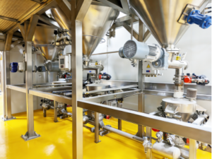
Walk the floor of a modern injection molding plant, and the automation is genuinely impressive — robotic arms handling part removal, in-mold sensors tracking cavity pressure in real time, smart machines adjusting process parameters shot to shot. Then walk over to the hopper on top of that same machine, and there’s a fair chance someone is still cutting open a bag by hand, or a maintenance tech is responding to a low-material alarm that’s been buzzing for ten minutes because nobody was near that machine when it went off.
This is a genuinely common pattern, and it’s an expensive one to leave unaddressed. Plants invest heavily in automating the molding machine itself while leaving material transfer, refilling, and material changeovers running on manual labor — creating what amounts to an automation island. The machine is fast, precise, and mostly unattended right up until it needs feeding, at which point a completely different, much less reliable process takes over. The costs that follow — labor overhead, material loss, dust, and machine utilization that never reaches its full potential — accumulate quietly enough that most plants underestimate them until someone actually measures them.
This guide breaks down what a central feeding system needs to do to close that gap — not just moving material from a bag to a hopper, but engineering the storage, distribution, and control logic that lets an injection molding floor run genuinely unattended on the material side.
Background: What Manual Feeding Actually Costs an Automated Molding Floor
Labor Cost Stays High, and Night Shifts Carry Real Staffing Pressure
A mid-sized injection molding operation running a dozen or so machines typically needs 2–4 dedicated material-handling workers covering unpacking, transport, refilling, and color/grade changeovers. Under a 24-hour, two-shift production schedule, the night shift still needs staff on hand to respond to low-material alarms — and this labor-heavy, physically demanding role is one of the harder positions to keep staffed as wage pressure and turnover both climb.
Material Loss and Mis-Feed Risk Translate Directly to Financial Loss
Storing raw material bags next to each machine and feeding through open pouring lets plastic pellets, masterbatch, and filler powder scatter and spill — industry experience with this kind of open handling commonly puts material loss in the 3–5% range. Beyond the loss itself, staging multiple material grades in close proximity increases the risk of manual misidentification; a mixed or wrong-grade feed can scrap an entire mold shot or an entire batch, and for higher-value modified plastics, a single misfeed event can represent a real, immediate financial loss.
Scattered Equipment Multiplies Maintenance Workload
Under a single-unit feeding model, every injection molding machine has its own dedicated feeder, filter, and hopper — so a floor of several dozen machines means several dozen independent power units and filtration assemblies. With filter cartridges, motors, and valve components varying by model across all that equipment, routine inspection, maintenance, and spare parts inventory management become a substantial workload, and it’s easy for some units to fall behind on maintenance and start failing more frequently.
Poor Housekeeping Makes 5S and Safety Compliance Difficult
Feeders, hoppers, and piping scattered across the floor with tangled routing, combined with continuous dust generation at powder-feeding points, leave floor-level residue and dust buildup that undermine shop cleanliness. That dust accumulation is also a genuine fire safety concern, and it’s a common point of deduction during environmental and safety inspections.
Production Continuity Gets Interrupted, Capping Real Machine Utilization
When a hopper runs low, the machine has to wait for a worker to physically arrive and refeed it before production resumes. During grade or color changeovers, workers need to clean and reload the hopper machine by machine, resulting in significant downtime. The result: nameplate machine capacity looks strong on paper, but actual productive uptime is continuously compressed by these manual dependencies.
Core Technical Explanation: How a Central Feeding System Actually Closes This Gap
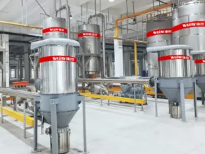
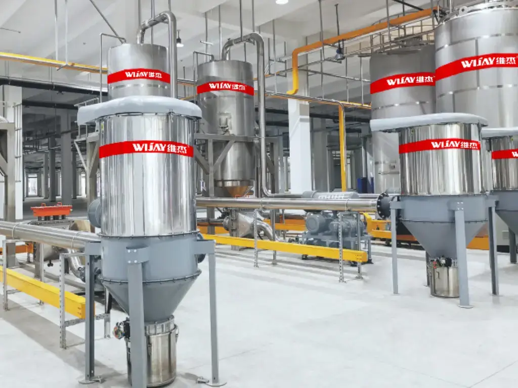
A central feeding system engineered for injection molding isn’t several single-unit feeders wired in parallel — it’s an integrated system built from seven core functional units working together: raw material storage, screening/impurity removal, a pneumatic conveying pipe network, intelligent switching distribution valve banks, a weighing/metering module, level-sensing modules, and a PLC central monitoring system.
The Full Operating Sequence
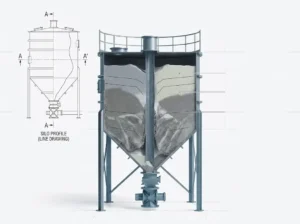
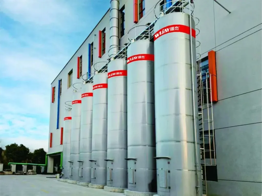
- Centralized intake and storage. Material arrives via bulk tanker, ton bag, or small-bag loading stations and is deposited into large indoor or outdoor storage silos, with different material grades stored in physically separated silos to eliminate the risk of cross-grade mixing at the source.
- Work-order-driven feed instructions. The control system reads the production work order and issues feed instructions based on each injection molding machine’s actual material requirement.
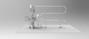
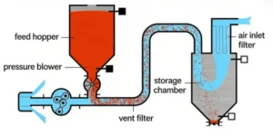
- Enclosed conveying with automatic routing. Material moves through sealed piping under negative or positive pressure, and intelligent distribution valves automatically select the correct pipe path to deliver the specified grade precisely to the receiving unit on each target machine.
- Automated level-based refill cycle. Level sensors continuously monitor each machine’s hopper level; a low-level signal automatically triggers refeeding, and a high-level threshold automatically stops supply — running as a fully automatic cycle with no manual intervention.
- Centralized monitoring and data logging. A central control platform monitors every feed point, displaying conveying status, hopper level, equipment alarms, and material consumption data in real time, with export capability that can integrate with a plant’s MES or ERP system for full-chain consumption tracking and traceability.
Single-Unit Feeding vs. Central Feeding: What Actually Changes on the Floor
| Factor | Single-Unit Feeding | Central Feeding System |
|---|---|---|
| Piping and equipment footprint | One feeder/filter/hopper per machine, dozens of independent power units | Consolidated distribution network from centralized storage |
| Refill trigger | Manual response to low-material alarm | Automatic, level-sensor-triggered refeeding |
| Grade/color changeover | Manual cleaning and reloading, machine by machine | Centralized switching at the control level |
| Maintenance points | Multiplies by machine count | Consolidated around the central system and distribution network |
| Traceability | Limited to whatever each unit logs individually | Centralized consumption data, exportable to MES/ERP |
Based on aggregated data across multiple deployed projects, plants moving from scattered single-unit feeding to a central feeding system commonly see on-floor piping count reduced by roughly 70% and the number of independent power units reduced by roughly 40% — a substantial compression in the ongoing maintenance burden described above.
Practical Field Troubleshooting & Decision-Making Guidance
Is This a Manual-Handling Problem You Can Fix, or a Sign You Need Central Feeding?
| Symptom on the Floor | Operating Fix | Sign: You Need a Central Feeding System |
|---|---|---|
| Occasional low-material stop on one machine | Improve alarm response procedure | Low-material stops recur across many machines regardless of staffing effort |
| One instance of misfeeding between similar-looking grades | Improve labeling/visual identification | Mis-feed risk is structural because multiple grades are staged near each other on the floor |
| A few filters/motors are overdue for maintenance | Catch up on the maintenance schedule | Maintenance backlog keeps recurring because the equipment count has outgrown what the team can service |
| Dust is visible near one feeding point | Add local containment | Dust and floor-level residue are a recurring, facility-wide 5S and safety inspection finding |
| Changeover on one machine took longer than expected | Review that specific changeover procedure | Changeover consistently consumes significant downtime hours across every machine, every grade switch |
Rule of thumb: if the same problem is isolated to one machine or one shift, it’s usually solvable with a process or staffing adjustment. If the same failure mode — starvation, misfeed risk, maintenance backlog, or changeover downtime — recurs across most machines on the floor, that’s a structural signal that the plant has outgrown manual, single-unit feeding.
Four Planning Pillars Before Committing to a Central Feeding Project
Most underperforming central feeding projects trace back to a planning gap, not equipment quality. Four areas need to be worked through before design begins:
| Planning Area | What to Confirm |
|---|---|
| Facility conditions | For new construction, reserve silo location, piping/cable tray routing, and floor penetration points during the civil works stage; for retrofits, survey actual floor-to-floor height, equipment placement, floor loading capacity, and available routing space on-site rather than applying a standardized layout |
| Material physical properties | Distinguish standard plastic pellets from high-wear glass-fiber-reinforced compounds, masterbatch powders, and moisture-sensitive modified materials — abrasive materials need wear-resistant elbows and valve rotors; hygroscopic materials need sealed, moisture-protected silos and piping |
| Capacity calculation with simultaneous-use coefficient | Don’t simply sum every machine’s maximum material draw — calculate peak hourly total consumption using an industry-typical simultaneous-use coefficient of roughly 0.6–0.8 for injection molding, and design in a 15–20% capacity margin for future equipment additions |
| Control system integration requirements | Confirm upfront whether the system needs to run on standalone local touchscreen control or integrate with the plant’s MES/ERP for work-order-driven automatic feeding and changeover — retrofitting this integration later adds avoidable cost |
Key Design & Operation Best Practices
- Separate material grades physically from the earliest storage stage — cross-grade mixing risk needs to be designed out at the silo level, not managed through operator vigilance on the floor.
- Size capacity against peak simultaneous demand, not the sum of every machine’s maximum draw — applying a realistic simultaneous-use coefficient prevents both under-sizing and unnecessary over-investment.
- Build in expansion margin from day one — a system running at its absolute limit turns a routine capacity increase into a disruptive redesign.
- Match wear-resistant and moisture-protection design to your actual material mix, not a generic industrial spec — glass-fiber-reinforced compounds and hygroscopic materials each carry different hardware requirements.
- Decide on the MES/ERP integration scope before equipment is specified — this is far cheaper to make upfront than to retrofit after installation.
- Treat the retrofit survey as non-negotiable for existing facilities — floor loading, ceiling height, and existing equipment placement all affect what layout is actually achievable, and a standardized plan applied without this data is a common source of installation-stage surprises.
Common Mistakes & Pitfalls to Avoid
- Automating the molding machine while leaving material handling manual. This is the exact automation-island pattern that caps real machine utilization even on an otherwise modern production floor.
- Underestimating material loss from open, per-machine storage and feeding. Losses in the 3–5% range are easy to overlook until they’re measured against a full year of production volume.
- Staging multiple material grades near each other without physical separation. This is a structural misfeed risk that no amount of operator training can fully eliminate.
- Sizing system capacity by summing every machine’s nameplate maximum. This leads to oversized, over-capitalized systems that don’t reflect how the floor actually operates.
- Applying a standardized layout to a retrofit project without a site survey. Floor loading, ceiling height, and existing equipment placement vary enough between facilities that a generic plan often doesn’t fit.
- Deferring MES/ERP integration decisions until after equipment is already specified. This is one of the more common sources of avoidable rework costs in central feeding projects.
FAQ
How much can a central feeding system actually improve machine utilization in an injection molding plant?
Based on data aggregated across multiple deployed projects, plants commonly report gains in effective machine utilization of 8–15% after eliminating manual refeeding waits and manual changeover downtime, though the specific improvement depends on your current baseline and production schedule.
Is a central feeding system worth it for a smaller injection molding shop with only a handful of machines?
It depends more on simultaneous material demand, grade variety, and shift structure than raw machine count — a smaller shop running many grade changeovers or requiring unattended night-shift operation can benefit as much as a larger floor running fewer, more stable production runs.
How does a central feeding system prevent material misfeeds between similar-looking grades?
Physically separated storage silos for each material grade, combined with system-level valve routing and program interlocks that prevent switching to the wrong pipe path, remove the manual visual-identification step that causes most mis-feed incidents.
Can a central feeding system integrate with existing MES or ERP systems?
Yes — this is a standard integration option, but it needs to be confirmed during the planning stage rather than assumed, since retrofitting MES/ERP connectivity after equipment is installed typically costs more than specifying it up front.
What’s the biggest planning mistake that causes central feeding projects to underperform after installation?
Most underperforming projects trace back to skipped upfront planning — insufficient facility survey, no material-specific hardware adaptation, capacity sized without a realistic simultaneous-use coefficient, or unclear control-integration requirements — rather than to equipment quality issues.
Ready to Close the Automation Gap on Your Molding Floor?
Competitive differences between injection molding machines are narrowing across the industry, which is making material-side automation an increasingly real source of competitive advantage. Share your material types, machine count, facility layout, and site distance so an engineering team can calculate your actual peak capacity requirement and propose a central feeding system design matched to your floor.