Automatic feeding systems now show up across plastics compounding, frozen bakery production, and fine chemical processing as the standard path to powder and granulate automation. And a recurring pattern shows up right alongside that adoption: plants select a system the way they’d buy a piece of commodity equipment — comparing vendor quotes side by side, checking nameplate throughput numbers, and signing off on whichever proposal looks most competitive on paper.
Then installation finishes, and the plant discovers the gap between “looks adequate on a spec sheet” and “actually works in this building, with this material, at this production schedule.” Plugging shows up on the first humid week. Conveying capacity falls short the day multiple lines run simultaneously. Equipment wears through faster than expected because nobody checked the material’s abrasiveness against the pipe material. None of these are equipment defects — they’re selection process failures, and they cost real time and capital to unwind after the fact.
This guide walks through the actual selection methodology that avoids this outcome: how to calculate real throughput requirements instead of relying on average daily output, how to assess material properties that actually drive hardware configuration, how to map site conditions before specifying equipment, and how to lock down a functional requirements list before scope creep blows up the budget mid-project.
Background: The Two Habits That Sink Most Feeding System Selections
Treating the System as a Shelf Product
The first common mistake is comparing automatic feeding systems purely on price, as if they were interchangeable commodity products. A conveying and feeding system’s performance depends entirely on how well its configuration matches your specific material, distance, and throughput profile — two systems quoted at similar prices can perform completely differently once they’re running your actual production conditions.
Sizing Off the Nameplate Instead of Real Plant Data
The second mistake is specifying capacity based on a vendor’s nameplate rating or the plant’s average daily output, without separating that from the plant’s actual peak-load conditions. A system that looks sufficient against average consumption commonly falls short the moment multiple production lines hit peak demand simultaneously — which is exactly the condition the system needs to be designed for, not the exception it’s expected to occasionally tolerate.
The result of either mistake, or both together, tends to look the same after startup: chronic plugging, insufficient conveying capacity under real load, moisture-driven caking, accelerated equipment wear, and a fault rate that turns a capital investment into an ongoing maintenance project. Fixing this after installation is a significantly more expensive correction than getting the selection methodology right upfront.
Core Technical Explanation: The Four Dimensions That Actually Determine Fit
1. Calculate Real Throughput — Separate Peak Consumption from Average Consumption
Capacity is the foundation the entire system design rests on, and confusing average hourly consumption with peak hourly consumption is one of the most common and consequential selection errors. Three data points need to be worked out before a system is sized:
- Maximum total hourly peak consumption — the combined material draw across all downstream production equipment running at full load simultaneously. This is the actual design baseline for the system’s conveying capacity, not the average of a typical shift.
- Equipment simultaneous-use coefficient — in real production, it’s rare for every downstream unit to run at full load continuously. Industry practice generally applies a coefficient in the range of 0.6–0.8 for injection molding operations and 0.7–0.9 for flour and bakery food production; for multi-reactor chemical processes, this needs to be confirmed against the actual production schedule and the number of simultaneous feed points rather than assumed.
- Reserved capacity for future expansion — a margin in the range of 15–25% above current peak demand is a reasonable planning target, since most plants expand capacity within a 3–5 year window, and a system running at its absolute limit forces a full redesign rather than an incremental addition when that expansion happens.
The real-world variation this produces is significant even within the same industry. Consider three anonymized food powder conveying projects: one, a listed frozen food producer’s system sized at 15 t/h to match 12 dough mixers running simultaneously at peak; another, a bakery ingredient producer’s system at 10 t/h matched to 8 simultaneous mixing units; and a third, a flour processing operation’s system at 8 t/h sized for peak demand across 3 production lines. All three are food powder conveying applications — the throughput specification differs by nearly double because the underlying downstream equipment count and simultaneous-use pattern differ, not because one plant simply “needed more capacity” in the abstract.
2. Assess Material Properties in Depth — This Decides Process and Hardware Configuration
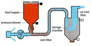
Material physical and chemical properties determine which conveying method applies — negative-pressure dilute-phase, positive-pressure dilute-phase, or dense-phase — and drive the full hardware specification, from silo design to rotary valve selection, pipe material, sealing, and dust control.
| Material Property | What to Confirm | Design Implication |
|---|---|---|
| Particle form | Large granule, small granule, standard powder, ultra-fine powder, or fibrous material | Granule and powder conveying logic differ substantially — a design for one doesn’t transfer to the other |
| Flowability | Poor-flowing, bridging/arching-prone materials | Storage silos need activated hoppers and anti-bridging devices, or discharge will be inconsistent |
| Moisture absorption / caking tendency | Hygroscopic materials like flour, yeast, powdered sugar | Silos need insulation/anti-condensation design; conveying air needs drying, or moisture ingress causes caking and blockage |
| Abrasiveness | High-hardness fillers such as fiberglass or calcium carbonate | Rotary valve rotors and pipe elbows need wear-resistant materials, or they wear through and perforate quickly |
| Hygiene/safety classification | Food-grade contact requirements; combustible dust classification | Food applications need 304/316 stainless steel contact surfaces with CIP compatibility; combustible powders need full explosion-proof design across motors, valves, and control cabinets |
| Material temperature | Hot, ambient, or frozen/low-temperature material | Different sealing structures and insulation design are needed, and hot material requires accounting for thermal expansion at pipe connections |
A large share of post-installation failures trace back to skipping this assessment entirely — taking a material name at face value and applying a generic standard configuration without testing these six properties against the actual incoming material.
3. Map Site Conditions Completely
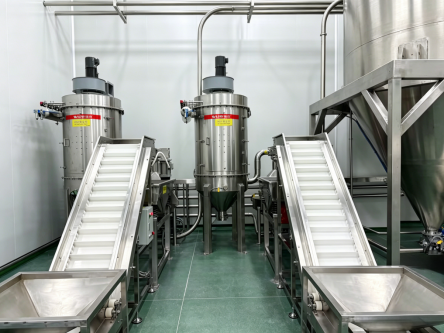
The same material can require a dramatically different system configuration depending on conveying distance and elevation change. Comparing two anonymized projects makes this concrete: one facility’s layout required 70 meters of horizontal conveying with a 30-meter vertical lift, while another required 50 meters horizontal with a 15-meter lift. The difference in distance and elevation between the two drove entirely different blower power and valve configuration specifications — despite both moving comparable food powders.
Site mapping needs to cover:
- Conveying distance and lift, including total elbow count — elbows increase conveying resistance, and more elbows mean more pronounced pressure loss that has to be compensated in the design.
- Raw material intake method — bulk tanker delivery, ton-bag unloading, or 25kg bag unpacking each point toward a different loading station design, whether that’s an outdoor bulk storage tank or an indoor silo.
- Facility space conditions — ceiling height, available equipment platform locations, cable tray and routing paths; for older facilities, floor loading capacity and fire compartmentalization need specific verification.
- Environmental constraints — whether the area requires explosion-proof or cleanroom-grade design, and any noise or dust emission limits the facility operates under.
4. Lock Down the Functional Requirements List Before Scope Creep Sets In
Confirming functional requirements in writing before the project starts is what prevents features from being added piecemeal during installation, which is a common driver of budget overruns. Items worth confirming explicitly:
- Automated weighing/metering requirements
- Screening needs for multi-component formulations
- Magnetic separation/impurity removal pretreatment
- CIP (clean-in-place) requirements for food applications
- Real-time silo level monitoring with high/low level alarms
- MES/ERP integration for production data traceability
- Automated purge system requirements for frequent multi-material changeover
Practical Field Troubleshooting & Decision-Making Guidance
Which Selection Step Was Skipped? A Post-Failure Diagnostic
| Symptom After Installation | Likely Root Cause | Which Selection Step Was Under-Assessed |
|---|---|---|
| System capacity insufficient when multiple lines run together | Sizing based on average consumption or single-unit nameplate rating | Real throughput calculation (peak consumption + simultaneous-use coefficient) |
| Chronic plugging during humid weather | No moisture/anti-caking design in silo or conveying air | Material property assessment (moisture absorption/caking) |
| Rapid wear or perforation in valves/elbows | Standard materials used on an abrasive filler-loaded compound | Material property assessment (abrasiveness) |
| Conveying capacity falls short of design value | Elbow count and distance-driven pressure loss not calculated | Site condition mapping (distance, lift, elbow count) |
| Budget overruns from features added mid-project | No written functional requirements list confirmed upfront | Functional requirements checklist |
| Inconsistent discharge from storage silo | No anti-bridging/activation design for a poor-flowing material | Material property assessment (flowability) |
Rule of thumb: if a fault traces back to a property or condition that was never assessed during selection, no amount of after-the-fact tuning fully resolves it — the fix requires revisiting that specific selection dimension, which is a more expensive correction than getting it right the first time.
A Rigorous Vendor Selection Process Should Include These Five Steps
| Step | What It Confirms |
|---|---|
| On-site facility survey | Actual layout, drawings, capacity data, and equipment placement — not assumptions from a floor plan alone |
| Material sample collection and testing | Flowability, moisture absorption, abrasiveness, and other properties specific to your incoming material |
| Conveying process calculation matched to conditions | Layout drawings and a complete equipment list based on your actual data, not a standard template |
| Simulation and technical report output | Documented hourly conveying capacity, metering accuracy, and other technical specifications before fabrication |
| Turnkey execution | Design, fabrication, installation, commissioning, operator training, and after-sales support as one accountable process |
A vendor unwilling to walk through these five steps — particularly skipping the material sample testing and simulation stages in favor of a quick standard quote — is a signal worth taking seriously during evaluation.
Key Design & Operation Best Practices
- Calculate peak simultaneous demand before finalizing capacity, using an industry-appropriate simultaneous-use coefficient rather than assuming full simultaneous load or relying on average output.
- Build in 15–25% expansion margin unless there’s a clear reason your production footprint won’t grow within a 3–5 year window.
- Test the actual incoming material against all six property dimensions — flowability, moisture behavior, abrasiveness, hygiene classification, particle form, and temperature — rather than applying a generic configuration based on the material’s name alone.
- Map conveying distance, lift, and elbow count on-site, not from a floor plan, since pressure loss compounds with both distance and turn count.
- Write the full functional requirements list down before the project starts — metering, screening, CIP, monitoring, MES integration, and purge capability all belong in that document, not added as change orders later.
- Weigh a vendor’s willingness to test, simulate, and document over their initial quote price — a lower price built on skipped assessment steps typically costs more once operating and rework expenses are counted.
Common Mistakes & Pitfalls to Avoid
- Sizing capacity from single-unit nameplate parameters instead of peak simultaneous demand. This is one of the most common causes of a system that’s technically installed but structurally undersized for real production.
- Ignoring moisture absorption and abrasiveness properties and applying a generic configuration. This shows up later as chronic plugging or accelerated equipment wear that traces directly back to a skipped material assessment.
- Failing to calculate resistance from elbow count and distance. A system specified without this ends up under-powered relative to its design target the moment it’s installed in the real layout.
- Cutting level monitoring, anti-bridging, purge, and dust control to reduce upfront budget. This looks like savings at the quote stage but tends to produce a higher total cost through frequent faults and rework over the system’s operating life.
- Not confirming the full functional requirements list before the project starts. Features added mid-project during installation are a common and avoidable source of budget overruns.
- Accepting a vendor’s proposal without a site survey, material testing, or simulation behind it. A standardized quote produced without these steps is a signal the design wasn’t actually engineered around your specific application.
FAQ
How do I calculate the right capacity for an automatic feeding system?
Start with the maximum total hourly consumption across all downstream equipment running at full load simultaneously, apply an industry-appropriate simultaneous-use coefficient (commonly 0.6–0.8 for injection molding, 0.7–0.9 for flour/bakery applications), and add a 15–25% margin for future expansion — rather than sizing off average daily output or a single machine’s nameplate rating.
Why do two plants handling the same material end up with completely different feeding system specifications?
Throughput and site conditions — not just the material — drive the design. Differences in the number of simultaneous downstream production units, conveying distance, elevation change, and elbow count between two facilities can lead to substantially different blower power, valve configuration, and overall capacity specifications even for comparable materials.
What material properties matter most when selecting a feeding system?
Particle form, flowability, moisture absorption/caking tendency, abrasiveness, hygiene/safety classification, and material temperature all directly affect conveying method selection and hardware configuration — skipping this assessment is one of the more common causes of post-installation failures.
Is it worth paying more for a vendor that does material testing and simulation before quoting?
Generally yes — a design validated against your actual material and site conditions is less likely to require costly rework after installation, and the additional upfront cost of testing and simulation is typically far smaller than the cost of correcting a chronic plugging or undersized-capacity problem later.
How much reserve capacity should an automatic feeding system have for future growth?
A margin of roughly 15–25% above current peak demand is a reasonable planning target for most operations expecting growth within a 3–5 year window, though the right number depends on your specific expansion plans.
Ready to Apply This Methodology to Your Plant?
The four dimensions above — throughput, material properties, site conditions, and functional requirements — only produce a reliable system design when they’re assessed against your actual plant, not a generic template. Share your material list, production line count and schedule, facility layout, and site distance so an engineering team can calculate real peak capacity and propose a system configuration matched to your specific operation.