A rotary valve rarely fails in a way that stops the line immediately. It wears slowly, opens clearance gradually, and changes the air balance in the conveying system long before anyone sees a broken part. By the time the line plugs, the receiver floods, or the blower is pushed to its limit, the valve has usually been sending signals for weeks. The problem is that those signals look like conveying problems, not valve problems — so operators chase the wrong symptom.
In positive-pressure systems, worn clearance leaks air backward into the feed hopper. In vacuum systems, worn clearance can leak material forward and make the system look temporarily more productive. Both paths end in the same place: unstable conveying, higher wear, and unplanned downtime. The plants that avoid that outcome are not doing anything exotic. They are reading the early signals and measuring clearance before the line forces the issue.

Why Rotary Valve Wear Shows Up as a Conveying Problem
The rotary valve does two jobs at once. It meters bulk solids into the conveying line, and it acts as an airlock between the line pressure and the upstream feed equipment. Wear affects both jobs, but the airlock function usually degrades first.
As the rotor edges, end plates and housing wear, the radial and end clearances increase. In a positive-pressure system, that extra clearance gives conveying air a path back into the hopper, screw feeder or transition chute. Air always takes the path of least resistance. Instead of doing useful work in the conveying line, a growing share of the blower output escapes upstream.
The result is not a dramatic valve failure. It is a slow loss of effective conveying air. The line may still run, but the pickup velocity drops, the solids loading becomes unstable, and the pressure profile starts to move in ways the operators did not plan for.
The hidden cost is not the valve — it is the air balance
A rotary valve that has lost clearance control can still turn freely and still meter material. That is why visual inspection often misses it. The valve looks fine. The line does not.
When effective air volume falls, the system loses margin. A line that was designed with a comfortable pickup velocity begins to operate closer to the material’s saltation point — the velocity at which particles start dropping out of suspension in a horizontal pipe. Once that margin is gone, small changes in feed rate, moisture or particle size can push the line into slugging.
Signal 1: Falling Conveying Rate in Positive-Pressure Systems
The most visible early signal in a positive-pressure system is an unexplained drop in conveying rate. It is tempting to blame the blower, the filter or the material. In many cases, the rotary valve is the source.
As air leaks back through the valve clearance, the main line receives less air than the blower is delivering. The pressure gauge may look normal or even slightly lower, because the system is not doing the same amount of conveying work. The feed rate may be steady at the valve, but the line cannot carry the material away at the same rate.
From unstable pickup to plug flow
When the effective air velocity falls below the material’s pickup requirement, the line starts to behave differently. Operators often hear it before they see it: an irregular “whoosh — whoosh” sound as material moves in bursts, stops, and moves again. That is slugging or plug flow, and it is a sign that the line is operating too close to its minimum velocity.
A mineral filler line we reviewed followed exactly that pattern. Throughput had fallen by roughly 12–15% over several weeks. The operators first increased the feed rate to compensate, which made the slugging worse. The blower was still delivering its rated volume, but a significant share was leaking back through the rotary valve end clearance. Once the clearance was measured against the manufacturer’s tolerance, the valve was clearly outside spec. Replacing it restored the air balance and the line returned to its original rate without any blower change.
What operators tend to do wrong
The common response is to add air, increase feeder speed or raise the pressure setpoint. Those actions can mask the problem temporarily, but they also increase velocity at the bends, accelerate wear and raise the risk of particle attrition. If the root cause is valve clearance, adding air is treating the symptom.
Signal 2: Vacuum Systems Hide Wear Until It Is Expensive
Vacuum conveying systems are less forgiving diagnostically. In a negative-pressure system, a worn rotary valve can leak material through the clearance rather than leaking air backward. The system may show a slight increase in vacuum level or conveying rate, which looks like improved performance. It is not. It is a sign that the valve is no longer separating the conveying line from the discharge path as effectively as it should.
The reason this is dangerous is that the change is subtle. In many vacuum systems, the rotary valve has to wear significantly before the throughput change becomes obvious. By then, the valve may be passing material into places it should not, and the receiver may be cycling differently. The line can go from “running fine” to “plugged” with very little warning.
A vacuum polymer powder case
On a vacuum-fed polymer powder line, the first complaint was not low rate. It was inconsistent receiver cycling. The vacuum level looked acceptable, and the conveyed tonnage was within range on most shifts. Then the line began surging and eventually plugged at a transfer point. Inspection showed rotor edge wear and material carryover through the valve clearance. The valve had been “working” — but it had stopped being a reliable airlock. The fix was not a larger vacuum pump. It was restoring the valve’s clearance and checking the upstream feed transition for wear.
The Signals Between Maintenance Windows
Most plants do not have the luxury of dismantling the conveying system every time throughput moves. That is why the early signals have to be read from normal operating data and operator observations.
Listen to the line. Irregular whooshing, pulsing or hammering sounds in a horizontal run usually mean slugging. If the sound appears only at higher feed rates, the line is already short of pickup velocity.
Watch the upstream feed point. In positive-pressure systems, air leaking back through the valve can fluidize material in the hopper, cause dusting at the feed transition, or make the screw feeder discharge unevenly. Operators sometimes describe this as “the hopper breathing.”
Trend the pressure and vacuum profile. A gradual shift in pressure differential across the line, or a vacuum receiver that cycles faster or slower than its baseline, is worth investigating before it becomes a blockage.
Record throughput at a fixed feeder setting. If the same valve RPM and the same material batch no longer produce the same conveying rate, the loss is in the air balance or the line condition.
These are not precision diagnostics. They are early-warning indicators. The precision step is clearance measurement.
The Definitive Check: Measure Clearance, Not Guess
The industry-standard way to confirm rotary valve wear is not a visual inspection. It is a clearance measurement compared with the manufacturer’s tolerance.
Measure both radial clearance between the rotor and the housing and end clearance between the rotor and the end plates. Record the values, compare them with the OEM specification, and trend them over time. A valve can look acceptable and still be outside its allowable clearance. A valve can also show visible polishing or minor scoring without being outside tolerance. The measurement is what separates the two.
| Check | What to do | What it tells you |
|---|---|---|
| Radial clearance | Measure rotor-to-housing gap at defined points | Whether air or material can leak around the rotor tips |
| End clearance | Measure rotor-to-end-plate gap | Whether leakage is developing at the faces |
| Tolerance comparison | Compare with OEM specification | Whether the valve is still within acceptable wear limits |
| Trend review | Compare with commissioning baseline | How fast wear is progressing and when to plan intervention |
If the measured clearance is clearly outside the manufacturer’s tolerance and the line is showing rate loss, slugging or material carryover, the decision is no longer “monitor.” It is “plan replacement or rebuild.” Continuing to run a valve that has lost clearance control simply moves the cost downstream — into blower energy, elbow wear, filter loading and lost production.
Where combustible dust is present, the inspection and housekeeping program should also align with the applicable combustible-dust safety standard [external link: combustible-dust safety standards]. Valve wear that allows dusting or air leakage can affect both housekeeping load and ignition-risk control.
What Good Rotary Valve Integration Looks Like
A rotary valve is not a standalone component bolted into a line. Its wear rate depends on how it is integrated with the feeder, the transition chute, the conveying line and the receiver.
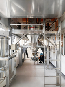
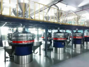
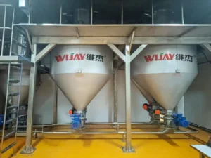
WIJAY approaches rotary valves as part of a complete enclosed conveying system. That means the valve is selected against the material’s abrasiveness, particle shape, bulk density and feed behavior — not just against a pipe size. The upstream transition is designed to avoid material accumulation and air leakage paths. The downstream line is sized so the valve is not compensating for a poor air balance. The receiver and filtration are matched to the actual dust load.
The practical advantages show up in service: fully enclosed material transfer from feed point to receiver, dust containment at the valve and transfer points, low material loss, and automation that ties valve speed, batch weight and conveying sequence into one control loop. For multi-industry plants handling different powders, the same system architecture can be adapted without treating every material as a new conveying problem.
WIJAY also builds the service side into the design. Clearance verification, wear-part replacement and rotor inspection are planned maintenance items, not emergency discoveries. That matters because rotary valve wear is not a question of whether it will happen. It is a question of whether the plant sees it early enough to schedule the fix instead of reacting to a plugged line.
For operators who want to connect valve condition to line performance, the practical next step is to establish a commissioning baseline and review it against operating data [internal link: WIJAY rotary valve service and clearance verification]. For plants designing a new line or correcting a chronic slugging problem, the valve should be reviewed together with the conveying system, not in isolation [internal link: WIJAY pneumatic conveying systems]. And where feed accuracy and dust containment are part of the production requirement, the valve and automation should be specified as one interface [internal link: WIJAY bulk material handling automation].
FAQ
How often should a rotary valve be inspected for wear?
There is no universal interval that fits every duty. Abrasive materials, high differential pressure and continuous operation justify more frequent clearance checks. A practical approach is to establish a baseline at commissioning, then trend clearance at planned shutdowns. Abrasive duty may justify inspection every 500–1,000 operating hours; mild duty can run longer. The trend matters more than a fixed calendar.
Can I adjust the clearance instead of replacing the valve?
Clearance is set by the rotor, housing and end-plate geometry. Once wear has opened the gap beyond the manufacturer’s tolerance, adjustment is usually not a repair. The valve needs new wear parts or replacement, and the surrounding transition should be checked for wear and air leakage paths.
Why does throughput drop while the blower still looks normal?
Because the blower is moving air, but not all of it is reaching the conveying line. In a positive-pressure system, worn rotary valve clearance lets air leak back upstream. The blower output can look normal while the effective pickup velocity in the line falls.
In a vacuum system, why would conveying rate increase before a blockage?
A worn valve can pass more material through its clearance, making the system appear to convey more for a period. That is not improved performance; it is loss of airlock control. The receiver cycling and vacuum profile usually become unstable before the line plugs.
When should a rotary valve be replaced rather than rebuilt?
If the housing, rotor or end plates are worn beyond the manufacturer’s repairable limits, replacement is the safer decision. If the wear is confined to replaceable components and the main geometry is within tolerance, a rebuild can restore performance. The decision should be based on measured clearance, not on how the valve looks.
CTA
If your line is losing rate, slugging at higher feed rates, or showing vacuum receiver behavior that no longer matches its baseline, do not start by adding air. Start by measuring the rotary valve clearance and comparing it with the specification. Send WIJAY the valve model, material data and operating symptoms, and we will help you determine whether the valve is the source — and what system-level fix will keep the line running without pushing wear downstream.