Walk through any modern chemical, food or pharmaceutical plant and you will find the same quiet infrastructure running behind the process: a pneumatic powder conveying system moving material from receiving and storage into the reactors, mixers, blenders and packaging lines. It is rarely the most visible equipment on site. It is almost always the system whose reliability determines whether the plant runs to schedule.
The reason it became standard is not marketing. It is that the alternatives — manual handling, open mechanical conveyors, bucket elevators, screw conveyors — carry costs that modern plants can no longer absorb: dust exposure, cross-contamination, material loss, labor dependency and the safety risk of combustible dust in open transfer points. A well-designed pneumatic system answers all of those at once. A poorly designed one creates new problems in their place.
This article walks through what the system actually contains, how material properties drive the design, where the losses hide, and what separates a system that becomes infrastructure from one that becomes a maintenance burden.
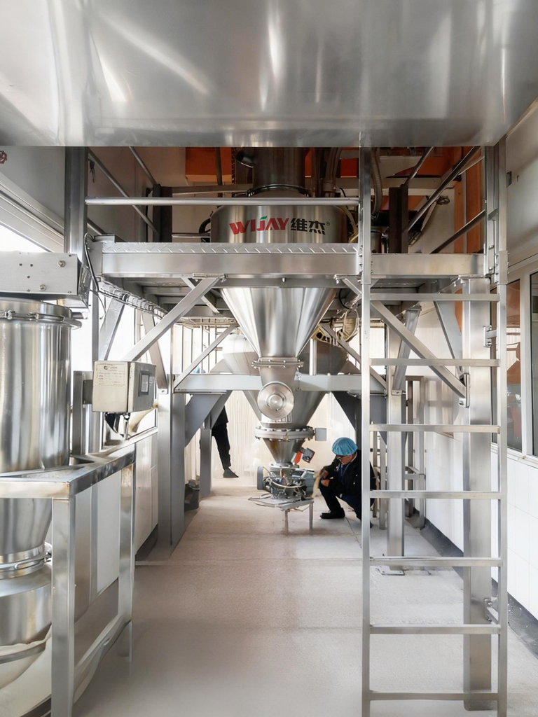
What a Pneumatic Powder Conveying System Actually Contains
A conveying system is not a blower and a pipe. It is a chain of equipment that has to function as one continuous containment boundary:
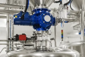
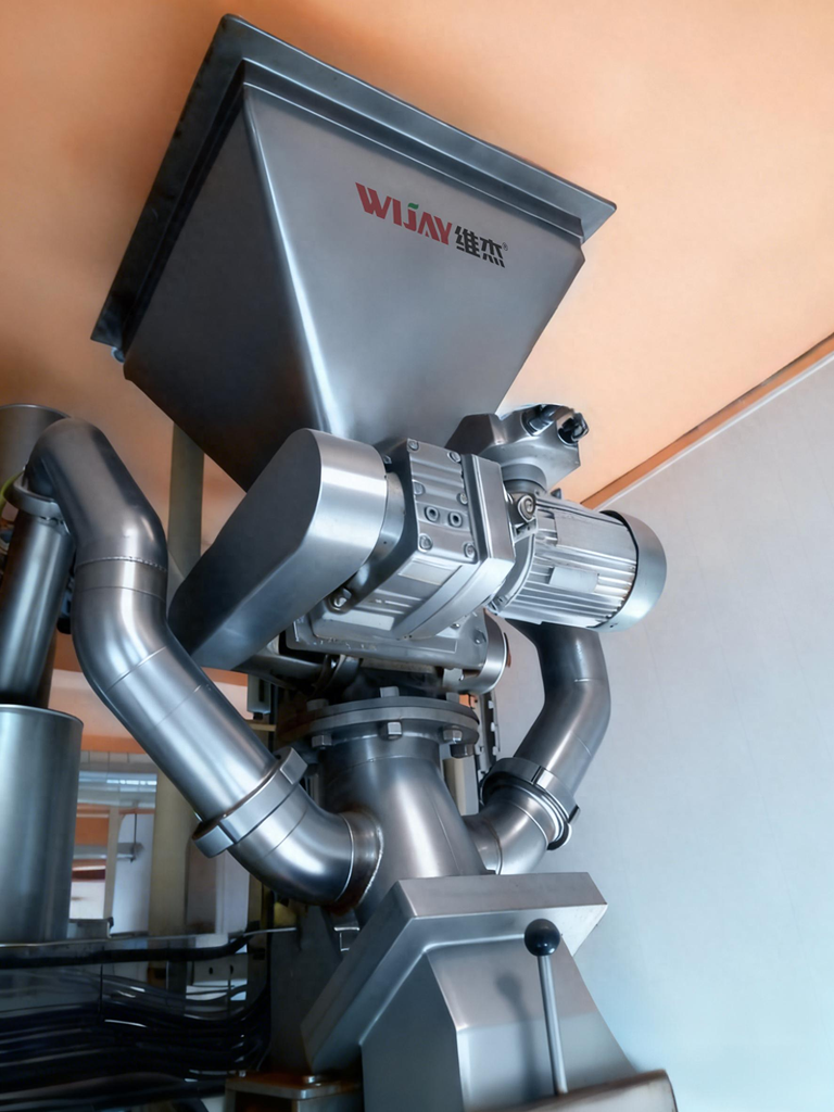
Feed point. A rotary valve, screw feeder or venturi eductor meters powder into the air stream. The feed point sets the solids loading, the air leakage rate and how evenly material enters the line.
Conveying line. Straight runs, bends, diverter valves and transitions. Line geometry sets velocity, pressure drop and wear.
Separation and receiving. A receiver, cyclone or filter separates powder from conveying air and discharges it into the next process step.
Dust collection and filtration. The filter must handle the actual dust load generated in the line, including fines created by particle attrition — not just the feed particle size.
Air supply. A rotary lobe or screw blower provides the conveying air. Its selection depends on the required pressure and flow envelope across the production cycle, not a single design point.
Control and automation. Batch weighing, dosing, sequence control and safety interlocks tie the mechanical chain into one reliable operating unit.
When any of these is selected in isolation, the system works on paper and underperforms in service. The most common failure pattern is a well-sized blower and line connected to an undersized receiver and filter, with a feed point chosen for price rather than for material behavior.
The Three Advantages — and the Engineering Behind Them
Most suppliers describe the benefits of pneumatic conveying in the same three phrases: labor savings, dust-free operation and flexible layout. Those benefits are real, but they are outcomes, not specifications. What matters is the design detail that produces them.
Labor savings depend on reliable automatic feed
A system that runs automatically saves labor. A system that trips on high-level alarms, plugs at the receiver or needs an operator to clear a feed transition does not. Continuous automatic operation depends on three things working together: stable feed metering, consistent pickup velocity, and a receiver discharge that empties fully on every cycle. If any of those is marginal, the line runs until it does not, and the labor savings disappear into troubleshooting.
On a food ingredient line, a system sold as “fully automatic” was running with an operator stationed at the receiver every shift. The receiver discharge was bridging because the discharge geometry and the aeration were not matched to the material’s cohesion. The system was conveying correctly and discharging unreliably. The labor saving existed on the proposal, not on the floor.
Dust-free operation depends on the whole boundary, not just the pipe
Enclosed conveying eliminates dust at the pipe. Dust still escapes at the feed point, at flanges, at the receiver discharge and at the filter vent. A system is only dust-free when every one of those points is designed as a sealed boundary, and when the filter is sized for the fines the line actually produces.
This matters beyond housekeeping. Fine powders with high surface-area-to-volume ratios carry higher dust explosion risk, and the hazard assessment for a conveying system has to account for the particle size that will actually exist in the line — including fines generated by attrition. A sealed boundary and a correctly sized filter are both a hygiene measure and a safety measure. Where combustible dust is present, the design should align with the applicable combustible-dust safety standard [external link: combustible-dust safety standards], and the containment strategy should be reviewed together with ignition-source control and pressure relief.
Flexible layout only pays off if the line is designed for the material
Pneumatic lines can route around equipment, change elevation and reach multiple discharge points. That flexibility is real, but it is not free. Every bend adds pressure drop and wear. Every change in direction creates a location where cohesive powder can accumulate. Every additional discharge point adds a diverter that has to seal.
A layout that is flexible on the drawing and poorly matched to the material produces a line that plugs at the same bend every week. Flexibility has to be designed together with the material’s saltation behavior, cohesion and abrasiveness — not applied afterward.
Material Properties Decide the System, Not the Other Way Around
The single biggest gap between a system that works and a system that disappoints is whether the material was characterized before the line was designed. Five properties drive most of the decisions.
Particle size and distribution. Fine particles stay suspended more easily in flowing air, which allows higher conveying rates at the same pressure drop. But finer particles also have higher surface-area-to-volume ratios, which increases cohesion and adhesion to pipe walls. The distribution matters as much as the average — a narrow, fine distribution can be harder to convey than a broader one, because the fine fraction dominates the cohesive behavior while offering few coarse particles to generate turbulence.
Bulk density. Bulk density determines the air volume needed to move the material, but the useful number is the compressible bulk density across the pressure range the line will see — not the loose-pour value. Granulated sugar is essentially incompressible under conveying pressure; sawdust compresses significantly and changes its interaction with air as it travels. Low-density fine powders such as fumed silica behave more like a gas-entrained cloud than a granular solid, and often need larger receivers and more filtration area than medium-density powders.
Gas interaction. Gas permeability is the ability of a packed bed to resist airflow through it. Fluidization is the ability of a material to take on fluid-like behavior as air is incorporated. Deaeration time determines how fast the material settles after fluidization. Dense-phase conveying depends on all three: a material that will not retain air and form a stable plug cannot support dense-phase operation, regardless of how attractive the wear numbers look.
Cohesion. Cohesion is the tendency of particles to stick to each other and to surfaces. It is driven by particle size, shape, moisture content and interparticle forces. A cohesive powder does not simply flow slower — it builds up on pipe walls, reduces effective line diameter and creates the conditions for a blockage that appears spontaneous but has been developing for weeks. Moisture content belongs in the same conversation, because humid plant air can move a material across the threshold from “conveyable with margin” to “conveyable only with dry-air purging.”
Abrasiveness and attrition. Abrasiveness is a function of particle hardness relative to the surface, impact velocity and solids loading. Wear concentrates at bends and diverters, and the dominant mechanism depends on impact angle: a shallow-angle strike can remove more metal than a perpendicular one. Attrition is the product-side counterpart — a friable material fractures on impact and generates fines, which change the particle size distribution, the cohesive behavior and the dust load in the receiving filter. Both wear pathways are minimized by the same logic: keep velocity as low as the material’s pickup and saltation requirements allow, and select bend geometry against the actual impact conditions.
Dilute Phase or Dense Phase: The First Design Fork
Every pneumatic system falls into one of two operating regimes, and the choice is a material verdict, not a preference.
Dilute phase keeps particles individually suspended in a high-velocity air stream. Air-to-solids ratio is high, the line runs above the material’s saltation velocity, and almost any dry material can be conveyed this way provided it can be fed into the line. The trade-off is velocity — typically in the range of roughly 4,000 to 6,000 ft/min — paid for in elbow wear, particle degradation and energy consumption.
Dense phase operates below the saltation velocity. Material moves as a concentrated bed — plugs, dunes or fluidized slugs — with solids loading that can reach 20 to 150 kg of solids per kg of gas. Lower velocity means less wear and less breakage, which is why dense phase is often the right answer for fragile, abrasive or already-friable products. But dense phase depends on the material’s ability to retain air, form a stable plug and release air at the receiving end. A low-permeability material will not support dense phase, no matter how favorable the wear numbers look.
Where the Losses Actually Hide
Material loss in a pneumatic powder conveying system rarely comes from a single dramatic failure. It accumulates in small, ordinary places.
Feed point leakage. A worn or poorly matched rotary valve leaks air and can leak powder. Air leakage changes the solids loading and can fluidize material in the hopper, causing dusting at the feed transition.
Receiver carryover. If the receiver or filter is undersized, fines pass through to the filter and are either captured as waste or emitted. On fine powders, carryover can be a steady, invisible loss.
Discharge bridging and hang-up. Powder that bridges in the receiver or hangs up in a transition is not lost to the environment, but it is lost to the batch. It shows up as short weights, inconsistent dosing and cleaning downtime.
Attrition-generated fines. Friable materials break down in the line. The fines change the product’s flow behavior and dust load, and in some products they are an off-spec fraction.
Cleanout and changeover loss. Systems that are hard to clean lose material at every product change. In multi-product plants, changeover loss can exceed conveying loss.
None of these appear on a datasheet. All of them are design decisions.
What a Well-Integrated System Looks Like
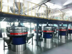
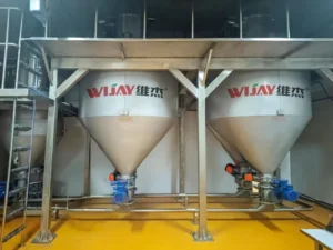
WIJAY designs pneumatic powder conveying systems as complete enclosed units, from feed point to receiver. The blower, feeder, line, receiver, filter and controls are selected together against the material’s bulk density, particle size distribution, cohesion, abrasiveness and the actual load profile of the plant.
The practical result is a system where powder is contained from the silo to the process. Positive-pressure and dilute-phase configurations handle long-distance and high-capacity duty. Custom layouts accommodate multi-point loading and discharge without treating each additional point as an afterthought. Automation — batch weighing, dosing and sequence control — is integrated at the system level, so the feeder, the air supply and the receiver operate as one loop rather than as independent skids.
WIJAY also designs for the parts of the life cycle that do not appear in the proposal: wear-part access, filter replacement, receiver cleanout and changeover between products. In multi-industry plants handling different powders, the same architecture can be adapted to different materials without re-engineering the whole line. That adaptability is what makes a pneumatic powder conveying system a long-term asset rather than a project that has to be re-solved every time the product changes.
For plants evaluating a new system, the practical first step is material characterization and a load-profile review [internal link: WIJAY pneumatic conveying system design]. For existing lines losing material or capacity, the first step is a boundary audit — feed point, receiver, filter and discharge — rather than a blower upgrade [internal link: WIJAY conveying system audit and service]. Where dust containment and automated material flow are production requirements, the conveying system and the automation should be specified together [internal link: WIJAY bulk material handling automation].
FAQ
What is a pneumatic powder conveying system used for?
It moves dry powders and granular solids through enclosed pipes using air, from storage or receiving into process equipment. It is used in chemical, food, pharmaceutical, mineral and polymer plants where dust containment, layout flexibility and automated material flow matter.
Dilute phase or dense phase — which is better?
Neither is universally better. Dilute phase uses higher velocity and suits a wide range of materials. Dense phase uses lower velocity and suits fragile or abrasive materials, but it depends on the material’s permeability and fluidization behavior. The choice is a material-property decision, not a preference.
Why does my system lose material even though the pipe is sealed?
Loss usually occurs at the feed point, the receiver discharge or the filter. Air leakage through a worn feeder, carryover of fines through an undersized filter, and bridging in the receiver discharge are common causes. The pipe is rarely the source.
Can one pneumatic powder conveying system handle multiple products?
Yes, if the system is designed with a velocity and pressure window that covers the most demanding material, and if cleanout and changeover are designed into the layout. A system tuned to a single free-flowing product often struggles with a cohesive or low-bulk-density product.
How do I know if my filter is undersized?
Common signs are frequent filter cleaning cycles, high pressure differential across the filter, visible dust at the receiver vent, and fines carryover. On fine powders, the filter often needs to be sized for the attrition-generated fraction, not just the feed particle size.
Does a pneumatic system work for abrasive materials like sand or fly ash?
It can, but the design has to account for wear from the start: lower velocity, appropriate bend geometry and surface materials, and a realistic maintenance plan for wear parts. For highly abrasive solids, dense phase or an alternative conveyor type may be the better answer, and the decision should be based on measured abrasiveness, not on a generic service label.
CTA
If your pneumatic powder conveying system is losing material, tripping on receiver alarms, or requiring an operator to keep it running, the problem is usually in the transitions, not the blower. Send WIJAY the material data, the line layout and the operating symptoms. We will help identify where the boundary is leaking — and what system-level configuration will contain the powder from silo to process, with the dust control, low loss and automation your production actually requires.