The pneumatic conveying system fan is usually selected late in the project, after the line layout, the feeder and the receiver have been fixed. The question at that point sounds simple: how much flow and how much pressure? The catalog answers it, the blower gets ordered, and commissioning proceeds. Then the line runs for six months, the product changes, the feed rate swings, and the blower turns out to be the component that cannot hold the operating point. The line starts slugging at low load, the pressure profile drifts, and the maintenance team is told the air supply is “marginal.”
In most of those cases, the blower is not undersized. It was selected against nameplate flow and nameplate pressure at a single design point that the plant almost never runs at. A pneumatic conveying system is not a steady-state load. Production rates move, silos switch, feeders fluctuate, and product grades change. The fan has to hold the conveying condition across that range, not just at the point printed on the datasheet.
This is the part of fan selection that catalogs do not cover, and it is where most of the expensive decisions get made.

Why the Fan Is a System Organ, Not a Bolt-On
The air delivered by the fan does not act in isolation. It interacts with the feeder, the conveying line, the bends, the receiver and the filter. Change the flow or the pressure and the entire flow regime in the line changes with it.
That is why fan selection cannot be separated from line design. A blower that looks correct on paper can still produce a line that slugs, wears elbows prematurely or loses pickup velocity at low load. The goal is not to pick a machine that can “blow hard enough.” The goal is to make the air source, the line and the material behave as one system across the actual operating envelope.
There is a second, frequently ignored constraint: the conveying load is not constant. A fan sized on nameplate flow plus nameplate pressure assumes the system always runs at its design point. In real plants, that assumption fails within the first production change.
Rotary Lobe Blowers: The Case for Simple, and What It Costs
Rotary lobe blowers have been used in pneumatic conveying for a century, and the reasons are practical. The rotors do not contact each other or the casing; a pair of timing gears maintains phase. The structure is simple, the machine is rugged, and the maintenance threshold is low. It is a device that handles dirty duty without asking for much.
The working principle matters for selection. A rotary lobe blower is a positive-displacement machine: each revolution moves a roughly fixed volume of air. The pressure is built externally, at the discharge, through constant-volume compression. The higher the system backpressure, the larger the pressure difference across the discharge, and the more violent that instantaneous pressure equalization becomes.
That principle produces three engineering consequences that belong in the selection conversation:
Pressure pulsation. Flow is delivered in pulses at a frequency tied to rotor speed. Three-lobe profiles are smoother than two-lobe, but pulsation cannot be eliminated. It travels downstream and affects rotary feeders, separators and dust collection equipment.
Higher temperature rise. Constant-volume compression dissipates part of the input energy as heat. At high pressure differentials, discharge temperature rises noticeably, and cooling and sealing need attention as single-stage differential approaches its limit.
An efficiency profile that depends on the operating point. Near the design point, a rotary lobe blower is competitive. When it runs far from the design point, or at low load for long periods, energy per ton conveyed grows.
None of this argues against rotary lobe blowers. In stable duty, moderate annual operating hours and investment-sensitive projects, they remain the most reliable cost-performance answer. The question is not whether they work. It is where they work without penalty.

Oil-Free Screw Blowers: The Internal-Compression Trade
Oil-free screw blowers take a different compression path. Air is compressed progressively inside the screw block, so pressure is largely established by the time the air reaches the discharge. The compression is continuous and smooth, and the output is close to pulsation-free.
The consequences cascade: lower pulsation, lower noise and vibration; lower compression losses, lower temperature rise and better specific power; and, with variable-speed direct drive, wide flow turndown. In food, pharmaceutical, PET and specialty chemical processes where oil contamination is not tolerated, an oil-free screw block with isolation seals can be designed to meet ISO 8573-1 Class 0 oil-free air.
Two points that marketing material tends to skip must be understood by the selector:
First, “screw is more efficient than lobe” is a conditional statement, not an identity. A screw blower has an internal compression ratio designed around a particular pressure. Efficiency is best when the operating pressure matches that internal ratio. Run far from it and under-compression or over-compression losses appear. The energy advantage has to be verified against the real pressure profile, not the best point on the sample curve.
Second, “oil-free” is not exclusive to screw machines. The compression chamber of a rotary lobe blower does not require lubricating oil either; the gearbox is a separate oil circuit. The core advantage of the oil-free screw is the compression process itself, not the label. During selection, check third-party oil-free certification and seal design directly rather than relying on marketing language.
Load Swings Are Where the Decision Gets Tested
Positive-displacement blowers share one useful property: flow is relatively insensitive to backpressure change. When feed increases and line resistance rises, system pressure adjusts upward while flow holds. That is the fundamental reason pneumatic conveying favors positive-displacement blowers over centrifugal machines. A centrifugal blower loses flow as pressure rises and can slide toward surge.
Rotary lobe and screw blowers are both positive-displacement machines and both handle load swings. The difference is the texture of the response. The lobe machine trades pulsation for pressure. The screw machine trades smoothness for efficiency.
On lines running near their conveying limit, or handling materials prone to bridging and accumulation, airflow smoothness directly affects plugging risk and process controllability. That is why fan evaluation cannot stop at average flow and average pressure. Stability belongs on the table.
The other under-estimated item is load factor. A fan is often sized for maximum demand, but the line spends much of its time at low load. Excess flow absorbed by a blow-off valve, bypass or throttling is electricity paid for nothing. A variable-speed direct-drive screw unit can match flow continuously to process demand, and that is where much of its payback comes from. This item rarely appears in the project justification; it appears in the operating curve.
Matching the Blower to the Pressure Profile
Pressure matching is the step most often reduced to a single number. It should be a profile.
For a screw blower, the real conveying pressure range and its variation must be compared with the machine’s internal compression ratio. If the line runs at a pressure far from the design ratio for most of the year, the efficiency advantage shrinks or disappears.
For a rotary lobe blower, confirm whether the machine will run at high differential pressure continuously. That is its most demanding and least efficient condition. A lobe blower that spends its life at the top of its pressure range is a blower that will ask for more maintenance and more energy than its datasheet suggests.
The practical approach is to plot the actual pressure and flow envelope over a production cycle, not to select at the maximum point. A blower that is slightly larger at the design point but holds efficiency across the envelope is usually the better investment than a machine that is optimal only at the nameplate condition.
What This Looks Like in the Field
On a mineral powder line, a rotary lobe blower was selected at the maximum conveying rate and maximum line pressure. At full production, the line ran acceptably. At the lower rates that dominated the second shift, the blower delivered more air than the line needed, and the excess was handled through a bypass. The energy cost was invisible in the project budget but obvious in the annual electricity review. The line also showed heavier elbow wear than expected, because the excess air raised velocity at the bends. The fix was not a larger blower. It was a blower and control scheme matched to the actual load profile.
On a vacuum-fed polymer powder system, the complaint was inconsistent receiver cycling and occasional plugging at a transfer point. The vacuum blower was delivering its rated performance. The problem was the interaction between the blower curve, the receiver sequence and the feeder. Once the blower was reviewed together with the receiver and the line, the cycling stabilized. The blower had been selected correctly in isolation and incorrectly as part of a system.
These are not unusual cases. They are the normal consequence of selecting a fan at a single point and commissioning it into a variable process.
How WIJAY Approaches the Pneumatic Conveying System Fan
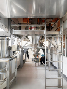
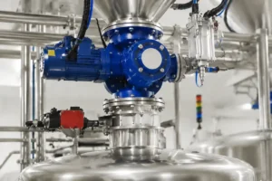
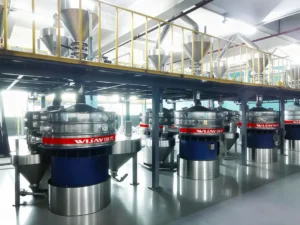
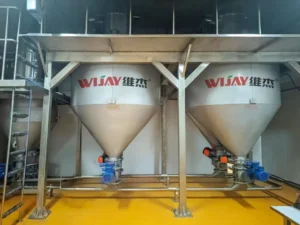
WIJAY treats the fan as part of a complete enclosed conveying system, not as a catalog item added at the end of the project. That means the blower is selected against the material’s bulk density, particle size, abrasiveness and conveying regime, and against the real load and pressure profile of the line.
The system-level view changes the selection. A fully enclosed WIJAY system contains the material from feed point to receiver, which stabilizes the dust load on the filter and reduces the air-volume variation the blower has to absorb. Positive-pressure and dilute-phase configurations are matched to line length, capacity and material behavior. Where the duty justifies it, the blower and the control scheme are specified together so that flow follows process demand rather than a fixed setpoint. Automation ties feeder speed, blower control and receiver sequencing into one loop, so the air source responds to the line instead of fighting it.
WIJAY also builds the service side into the selection. Blower inspection, seal condition and control calibration are planned maintenance items. That matters because the fan is the component whose degradation is easiest to misread as a line problem. A blower that has drifted from its operating point looks like a conveying fault until someone checks the air side.
For plants comparing blower technologies against an existing line, the practical first step is to log the real pressure and flow envelope over a production cycle [internal link: WIJAY blower and air-supply review]. For new systems, the blower should be reviewed together with the feeder, line and receiver, not after they are fixed [internal link: WIJAY pneumatic conveying system design]. Where dust containment and automated material flow are part of the production requirement, the air supply and the automation should be specified as one interface [internal link: WIJAY bulk material handling automation].
FAQ
Is a rotary lobe blower or an oil-free screw blower better for pneumatic conveying?
Neither is universally better. Rotary lobe blowers are cost-effective in stable duty and moderate operating hours. Oil-free screw blowers offer lower pulsation, lower temperature rise and better part-load efficiency when the pressure profile matches their internal compression ratio. The decision depends on the load profile, the pressure range and the annual operating hours, not on the technology label.
Why does my blower look fine on the gauge but the line still slugs?
Because the gauge shows the blower’s output, not the effective air reaching the conveying line. Air leakage through a worn rotary valve, a restricted filter or a feeder transition can reduce pickup velocity while the blower appears normal. Slugging at low load often points to a load-profile mismatch rather than a blower failure.
Can I select the fan at the maximum conveying rate and pressure?
You can, but it usually produces a machine that is efficient only at a condition the plant rarely runs. Selecting at the maximum point tends to oversize the blower at normal load and can push excess air through the line, raising velocity at bends and increasing wear. The better basis is the full pressure and flow envelope over a production cycle.
Does an oil-free screw blower always save energy compared with a rotary lobe blower?
No. The savings depend on whether the operating pressure matches the screw’s internal compression ratio and whether the line runs long hours at part load. A screw blower running far from its design pressure can lose much of its advantage. Verify with the real pressure profile, not the best point on the sample curve.
How does pulsation from a rotary lobe blower affect the conveying line?
Pulsation travels downstream and can affect rotary feeder metering, separator performance and dust collection. On lines running near their conveying limit or handling materials prone to bridging, smoother airflow can reduce plugging risk. This is one reason fan selection should be reviewed together with the feeder and receiver, not in isolation.
CTA
If your line is slugging at low load, wearing elbows faster than expected, or running a blower that no longer matches its original operating point, start with the air side before changing the line. Send WIJAY the material data, the real pressure and flow envelope, and the current blower model. We will help determine whether the fan is the constraint — and what system-level configuration will hold the conveying condition across your actual production cycle, not just at the nameplate point.