Introduction: The Valve That Makes or Breaks Your Conveying System
Pressure instability in a pneumatic conveying system rarely starts in the pipe. It starts at the transfer point—where material leaves the hopper and enters the airstream. And at that transfer point, the rotary valve has to do two jobs simultaneously: meter material at a predictable rate and maintain the pressure boundary the rest of the system depends on.
If it cannot hold that balance, conveying velocity falls. Line plugs become more frequent. Upstream equipment surges. Production slows. Energy costs spike.
A rotary valve looks simple—a multi-vane rotor spinning inside a housing. But its performance is shaped by dozens of variables: product characteristics, pressure differential, rotor speed, operating clearances, and the overall design of the conveying system. Selecting the correct valve is far from straightforward.
This guide is written for engineers who specify, maintain, or troubleshoot pneumatic conveying systems. We will not sell you a valve. We will show you how to choose the right one.
Why Most Rotary Valve Selections Fail
Most pneumatic conveying system problems begin at the rotary airlock. Here is what that looks like in practice:
Air leakage is the most common failure mode. Every rotary valve leaks some air—it is a mechanical reality. But when clearances are too large or the valve is underspecified for the pressure differential, leakage becomes excessive. High-pressure air blows past the rotor, creates turbulence at the inlet, and prevents light or low-bulk-density materials from filling pockets consistently. The result: effective capacity drops even when the drive runs at the expected RPM.
Wear is the second major issue. Rotary valve wear occurs internally and slowly, which makes it difficult to detect. By the time you notice a drop in conveying rate, the damage is already done. Abrasive materials accelerate this process—rotor tips erode, clearances open up, and leakage increases in a vicious cycle.
Material build-up is the third problem. Moist or sticky products accumulate in rotor pockets and on the bore. This reduces fill efficiency, creates dead zones, and eventually leads to blockages.
A poorly selected rotary valve does not just reduce efficiency. It compromises explosion protection, creates NFPA compliance exposures, and drives up maintenance costs.
Pressure Differential: The First Selection Criterion
The most demanding environment for a rotary valve is a pressure differential application. Material flows from a higher-pressure zone to a lower one—or vice versa—and the valve must maintain a seal tight enough to prevent meaningful air loss across the rotor.
For high-pressure pneumatic conveying—often up to 15 or even 22 PSIG—the mechanical load on the valve increases significantly. Standard valves may experience shaft deflection or bearing failure under these loads.
The engineering challenge comes down to clearances. To function as an airlock, the gap between the rotating vanes and the stationary housing must be extremely tight—often less than 0.0079 inches (0.2 mm) for high-pressure applications. Those tolerances support throughput stability by limiting leakage while still allowing reliable rotation.
As a rule of thumb: rigid rotor tips should be used in all applications where the pressure differential exceeds 2 psi. Below that threshold, more flexible tip materials may be acceptable.
Valve Configurations: Drop-Through vs. Blow-Through
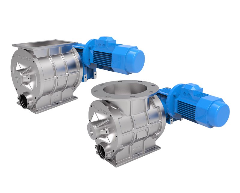
The two primary configurations for pneumatic conveying are drop-through and blow-through valves.
Drop-through valves are the most common style, with one port at the top (inlet) and one at the bottom (outlet). Material enters from the top, fills the rotor pockets, and discharges downward as the rotor turns. These are versatile and used across many industries for bulk powder handling.
Blow-through valves are designed specifically for pneumatic conveying. Pressurized air blows into the housing, pushing material from the inlet through the discharge port directly into the conveying line. This configuration eliminates the transition duct that can create dead zones and turbulence—a significant advantage in food-grade and sanitary applications.
For pneumatic conveying, the blow-through design is generally preferred because it handles the specific mechanical requirement of discharging material directly into a pressurized airstream without bridging or packing in the rotor pockets.
Rotor Design: Matching the Rotor to the Material
The rotor is the heart of the valve. Different materials demand different rotor configurations. Here is how to match them:
Closed-end rotors feature pockets that are fully closed by plates at each end. This design protects the end plates and outboard bearings from material contact, making it ideal for abrasive or dusty products. The eight-blade closed-end rotor design provides superior two-blade sealing without sacrificing pocket capacity.
Open-end rotors have pockets that are fully open on both ends. These are simpler and less expensive but offer less protection for bearings and seals. They are suitable for free-flowing, non-abrasive materials.
Radial pocket rotors (also called U-shaped or pocket-style rotors) minimize material accumulation at the vane roots. For sticky or cohesive materials that tend to pack in standard V-shaped pockets, this design is more reliable.
Flexible-tip rotors use bolted rubber tips—available in neoprene, silicone, or polyurethane. These are the preferred choice for fibrous materials like flakes or碎片, as well as for applications requiring a tighter seal at lower pressure differentials.
Adjustable-tip rotors allow tip replacement when wear occurs. While not suitable for food or sanitary applications due to potential contamination points, these are extremely versatile for handling moderately abrasive materials in industrial settings.
Bolt-on serrated-tip rotors are designed for sticky or cohesive materials. The serrated edges provide a self-cleaning action, scraping material from the housing bore as the rotor turns. Two serrated tips are arranged opposite each other to achieve full cleaning coverage.
Construction Materials and Coatings: The Longevity Decision
The time you spend selecting the right materials and coatings is time you will not spend on maintenance later. Here is what matters:
Housing material must be compatible with both the product and the process environment. For sanitary applications—food, pharmaceutical, and dairy—stainless steel construction is non-negotiable. For general industrial use, cast iron or fabricated steel may be sufficient. The body and end covers must be heavy-duty enough to withstand the pressure differential and precisely machined to very tight tolerances.
Internal coatings reduce accumulation and wear. Tungsten carbide coatings protect against abrasion from minerals, cement, and other hard materials. Non-stick coatings (PTFE or similar) help sticky materials slide through the valve and make cleaning easier. High-quality valves come with factory-applied coatings—not field-applied afterthoughts.
Temperature rating matters more than many engineers realize. Standard valves may be rated to 150°F or 350°F, but high-temperature applications can reach 500°F or even 1,000°F. Thermal expansion changes clearances—and if the valve is not designed for your operating temperature, clearances will open up as the housing expands, increasing leakage.
Sealing: The Forgotten Engineering Detail
Shaft seal leakage is one of the most common issues in rotary valves. In many cases, the root cause is not the seal itself but rotor wear that increases internal clearances.
The best seal design for pneumatic conveying is the packless sleeve-type shaft seal with a triple-barrier design:
- A primary seal that prevents material migration
- A secondary barrier that contains any leakage
- A vent or collection point that allows monitoring
This design eliminates the need for time-consuming end plate adjustments and provides an extra layer of safety against contamination—critical in food and pharmaceutical applications.
For high-pressure applications, some manufacturers offer self-sealing designs where the product itself packs into the clearance gaps, reducing leakage by approximately 50%.
The Selection Framework: A Practical Checklist
When specifying a rotary valve for pneumatic conveying, work through these questions in order:
1. What is the pressure differential? This determines the required clearance tolerance, rotor tip rigidity, and housing strength. High-pressure applications (>15 PSIG) demand heavy-duty construction.
2. What are the material properties? Bulk density, particle size, abrasiveness, flowability, moisture content, and temperature all influence rotor selection, materials, and coatings.
3. What is the required throughput? This determines valve size and rotor speed. Remember that fill factor is rarely 100%—most manufacturers specify displacement at 80% fill factor. For positive-pressure conveying, de-rate the efficiency to 0.65–0.70 due to air leakage.
4. What is the configuration? Drop-through for gravity-fed applications; blow-through for direct integration with the conveying line.
5. What are the sanitary requirements? Food, dairy, and pharmaceutical applications require stainless steel construction, sanitary seals, and designs that eliminate dead zones and allow thorough cleaning.
6. What is the maintenance strategy? Consider rotor accessibility, tip replaceability, and cleaning requirements. Quick-clean designs with slide-out rotors reduce downtime significantly.
Conclusion: Engineer the Selection, Not the Compromise
The rotary valve is a small component with an outsized influence on system performance. It meters product, maintains pressure differentials, controls air leakage, and in some designs, contributes to explosion isolation. It must be selected with the same level of engineering rigor as the blower package or the conveying line.
Most plants do not fail because they bought the wrong blower. They fail because the rotary valve was an afterthought.
Getting the selection right means understanding your material, your pressure differential, your throughput requirements, and your operating environment. It means choosing the right rotor, the right coating, the right seal, and the right configuration—not because the spec sheet says so, but because your production line depends on it.
At WIJAY Systems, we have spent years working with bulk solids, pneumatic conveying, and powder automation equipment across industries—from food and pet food to pharmaceuticals and chemicals. We have seen what works and what fails. We do not sell off-the-shelf solutions; we engineer the right valve for your specific application.
If you are specifying a rotary valve for pneumatic conveying and want to get it right the first time, talk to us. We will help you work through the material properties, the pressure differential, the throughput calculations, and the configuration details.
Contact WIJAY Systems for a professional consultation on your pneumatic conveying application.
FAQ
What is the difference between a rotary feeder and a rotary airlock valve?
A rotary feeder is the broader category—its function is volumetric metering. A rotary airlock valve is a rotary feeder that also maintains a differential pressure seal. In pneumatic conveying, you need both functions: feed AND seal. A standard rotary feeder that cannot hold a pressure differential will bleed air across the rotor, degrading conveying performance.
How tight should rotor-to-housing clearances be?
For high-pressure applications, clearances must be less than 0.0079 inches (0.2 mm). Lower-pressure applications may tolerate wider clearances, but tighter clearances always mean less leakage and better conveying performance.
How do I know if my rotary valve is leaking?
Many rotary valves come with a side vent port. You can open this port (with the valve stopped) and measure the leakage rate through the vent line. You can also install pressure probes or airflow measurements before and after the valve. A drop in conveying rate is the most common indicator of wear and increased leakage.
What rotor type is best for sticky materials?
Radial pocket rotors (U-shaped pockets) minimize material accumulation at the vane roots. For extremely sticky materials, bolt-on serrated-tip rotors provide a self-cleaning action that scrapes material from the housing bore.
Can I use a standard-duty rotary valve for pneumatic conveying?
Standard-duty valves are designed for gravity flow or low-pressure differential applications. They are not suitable for abrasive products, high temperatures, or large pressure differentials. Pneumatic conveying requires a heavy-duty valve that can withstand the pressure differential and material wear.