Every plant engineer who’s specified a conveying line retrofit knows this moment: the layout drawing is done, the equipment is picked, and then someone walks the actual floor and finds a support column, a mezzanine edge, or a ceiling height restriction sitting exactly where the clean horizontal-then-vertical route was supposed to go. The easy fix on paper is an inclined pipe run cutting the corner. The harder question — the one that doesn’t get answered by a rule of thumb — is whether that incline will run clean for the next ten years or start dropping product velocity, spiking pressure, and plugging the line six months after startup.
This is one of the most argued layout decisions in pneumatic conveying systems design, and until recently, most of the guidance around it was genuinely just opinion dressed up as engineering practice. Nobody wants to be the engineer who signed off on a pipe run that now needs an unplanned shutdown, a full material purge, and a redesign six months into production — but “avoid inclines” isn’t always a real option once you’re working inside an existing building.
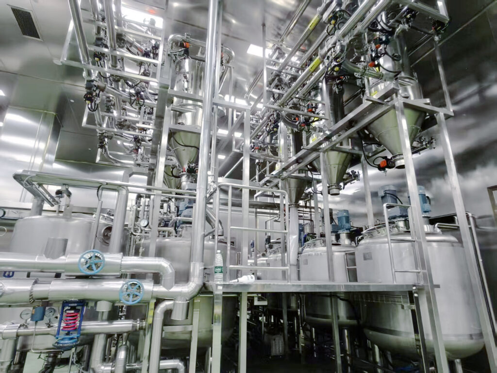
Why Pipe Routing Rules Exist — and Why They Sometimes Conflict
Bulk solids conveying has always leaned on a handful of field-tested layout principles:
- Take the most direct path — shortest distance, fewest elbows.
- Avoid back-to-back elbows, which compound turbulence and pressure loss.
- Run horizontal or vertical wherever possible — inclined pipe has traditionally been treated as the layout of last resort.
The problem is these rules don’t always agree with each other. A direct diagonal route is genuinely shorter than a horizontal-plus-vertical dogleg around the same obstacle, which lowers operating pressure and energy draw. Where elevation change is modest, an incline can also eliminate the back-to-back elbow pair that a horizontal-vertical-horizontal route would otherwise require. So the honest answer to “should this run be inclined” has never been a flat yes or no — it’s a trade-off between path efficiency and incline penalty, and most plants have had no real data to make that trade-off with.
What Actually Counts as an Inclined Run
Before evaluating the trade-off, it helps to define the boundary. In pneumatic conveying system design, a run is generally classified as inclined when:
- A horizontal pipe rises more than roughly 10° (thresholds in published literature range 7°–15°)
- A vertical pipe deflects more than roughly 10° off true vertical
- A horizontal pipe drops more than roughly 10°
Recent comparative testing — conducted by German engineering firm Olar — focused specifically on uphill runs between 10° and 45°, since anything steeper is generally treated as inclined-vertical for design purposes. That focus matters: uphill and downhill inclines behave completely differently. On a downhill run, gravity assists material movement — in some cases product will slide under gravity alone, with minimal air assistance required. On an uphill run, gravity actively resists movement, and every degree of incline adds resistance the airflow has to overcome. That asymmetry is why uphill incline is the real design risk, and where the test data below is focused.
The Test: Real Materials, Real Pipe, Side-by-Side Comparison
The test rig fed material from a weigh belt through a rotary feeder, then split it across two parallel routes to the same endpoint — one following a conventional horizontal/vertical layout, the other routed through a 50-foot section inclined at 21°. Four materials were run through both paths, chosen specifically to span a range of density, particle size, and flow behavior: glass-fiber reinforced pellets, green coffee beans, chia seeds, and natural brown sugar. Each material ran at two different conveying rates, and each configuration was tested in both dilute-phase and dense-phase conveying, since the two conveying modes behave very differently under incline stress.
Pressure sensors were staged along both routes — one set capturing total zone pressure drop from feed point to the point where the two paths rejoined, and a second set isolating an equal-length segment for direct apples-to-apples comparison. It’s worth noting the inclined route was also inherently 14 feet shorter than the conventional path (the geometric shortcut of a diagonal versus a right-angle route) and eliminated one 90° elbow — both factors that work in the incline’s favor and had to be separated from the incline penalty itself. Dense-phase materials ran on continuous feed equipment for steady-state data; brown sugar, tested in batch dense-phase mode with downstream air boost, was averaged across multiple runs.
What the Data Actually Shows
Dilute-Phase Conveying: The Incline Penalty Is Real and Material-Dependent
In dilute-phase systems, the inclined run required 3% to 45% more airflow than the conventional route, depending on material and conveying rate. Pressure drop across the inclined section ran 1.2 to 2.5 times higher than the equivalent horizontal segment. System stability also measured lower on the inclined path — though the effect was modest at low loading rates and became more pronounced as throughput increased. For a plant running dilute-phase conveying near its airflow ceiling, that’s not a rounding error — it’s the difference between a line that runs clean and one that starts surging.
Dense-Phase Conveying: One Number Decides Everything
The dense-phase results point to a single governing variable: the material’s slide angle relative to the pipe’s incline angle.
- When the material’s slide angle is greater than the pipe incline — brown sugar’s 30° slide angle against the 21° pipe incline, for example — pressure impact stayed minimal, at 1 to 2.3 times the flat-pipe baseline, with no additional airflow required.
- When the material’s slide angle is less than the pipe incline — green coffee beans, with a roughly 20° slide angle against the same 21° incline — pressure drop spiked to 4.5 times baseline, and the system needed 35% to 45% more airflow just to keep material moving.
That’s a five-degree difference in material behavior producing a fourfold difference in pipe stress. It’s also exactly the kind of variable that doesn’t show up on a standard pipe layout drawing, and exactly the kind of number a plant only discovers the hard way — after startup, after the plugging starts, after the shutdown.
Design Guidance: How to Actually Decide
- Check the material’s slide angle against the planned pipe incline before finalizing the route. This single comparison predicts most of the downstream risk.
- If slide angle exceeds incline angle, an inclined run is generally safe to use, with manageable pressure and airflow impact — particularly in dense-phase design.
- In dilute-phase systems, treat inclined runs with more caution across the board, and build in airflow adjustment headroom regardless of material, since even favorable materials showed measurable pressure and stability penalties.
- Weigh the geometric win against the incline penalty case by case — a shorter path and one fewer elbow are real advantages, but they only pay off when the material behavior supports the incline.
Where This Fits Into a Full System Design
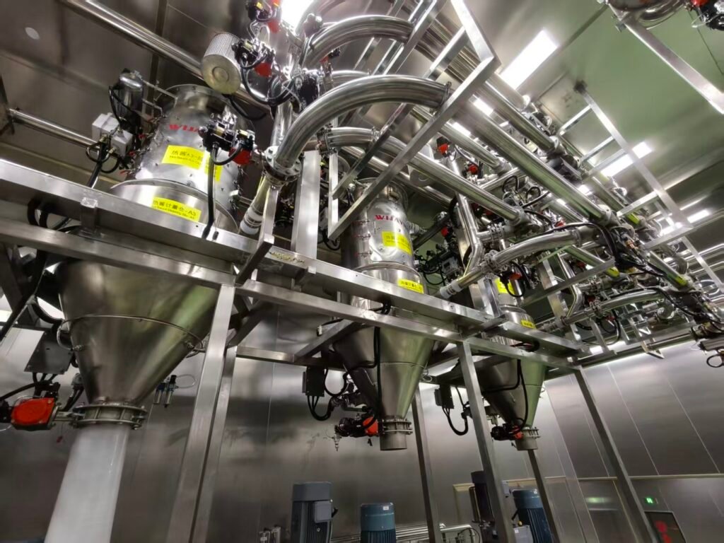
Getting the incline decision right on paper still depends on getting airflow, pressure staging, and material behavior right across the entire line — not just the sloped section. This is the level of detail WIJAY Systems builds into every conveying line we spec: fully enclosed, dust-free pneumatic conveying engineered around the actual material’s flow characteristics, not a generic layout template. We’ve routed lines around the same columns, mezzanines, and height restrictions that force this exact trade-off, and we size airflow and equipment for the material you’re actually running — not a best-case assumption that falls apart six months after startup. Combined with integrated, automated dosing and low-loss transfer across the full line, that’s what keeps a pneumatic conveying system running clean for years, not just through commissioning.
FAQ
What angle counts as an inclined pipe in pneumatic conveying? Generally, a horizontal pipe rising or falling more than roughly 10°, or a vertical pipe deflecting more than roughly 10° off true vertical — though published thresholds range from 7° to 15° depending on the source.
Is it safe to use inclined pipe in a dilute-phase conveying system? It can be, but testing shows dilute-phase systems need 3% to 45% more airflow on inclined runs and see meaningfully higher pressure drop, so incline should be used cautiously and with airflow headroom built in.
How do I know if my material is safe to run through an inclined pipe? Compare the material’s slide angle to the planned pipe incline angle. If the slide angle is greater than the incline, pressure and airflow impact are typically minimal. If it’s smaller, expect a sharp increase in both.
Why does an inclined pipe behave differently uphill versus downhill? On a downhill run, gravity assists material movement, sometimes with minimal air needed. On an uphill run, gravity resists movement, and every degree of incline adds resistance the airflow has to overcome — which is why uphill runs are the real design risk.
Talk to an Engineer Before You Route the Line
If your layout has a column, a height restriction, or an elevation change that’s pushing you toward an inclined run, don’t guess at the airflow penalty. WIJAY Systems can model your actual material’s slide angle against your planned pipe geometry and size the pneumatic conveying system — dilute or dense phase — to run clean at that incline, not just at commissioning. Talk to our engineering team about your layout.