When a pneumatic conveying system goes down, the instinct is to find the blockage, clear it, and restart. That response gets the line moving — but it rarely prevents the next shutdown. The most persistent troubleshooting problems in pneumatic material handling systems are not equipment failures: they are design mismatches that surface as operational symptoms.
This guide works through the six most common failure modes in pneumatic conveying system troubleshooting, explains the root causes engineers most frequently miss, and identifies the system design decisions — and supplier choices — that eliminate recurring problems rather than managing them.
How Does a Pneumatic Conveying System Work — And Where Failures Start
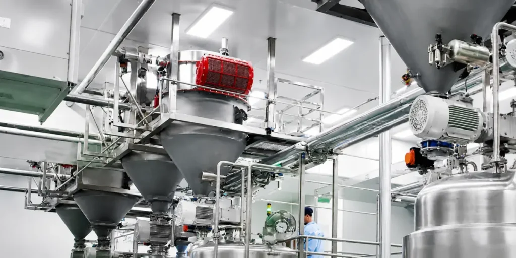
A pneumatic conveying system uses an enclosed pipeline to transport bulk materials using either positive pressure or vacuum. All piping, transitions, and components are airtight to maintain system performance and eliminate uncontrolled leaks — keeping materials fully isolated from the external environment while maintaining consistent velocity and pressure for stable conveying across long distances.
The reliability of a pneumatic conveyor is determined by the adequacy of its design and how effectively the design parameters and operating conditions align with the physical properties of the material being conveyed. When that compatibility breaks down, issues such as frequent blockages, unstable flow, particle degradation or attrition, and premature wear appear.
That final sentence is the most important concept in troubleshooting pneumatic conveying systems. Almost every recurring failure traces back to one of four original design decisions: air velocity selection, pipeline routing, feeder specification, or system architecture for multi-drop or multi-source configurations.
Failure 1: Pipeline Blockages — The Most Misdiagnosed Problem
Pipeline blockage is the most common call in pneumatic conveying troubleshooting — and the most over-simplified. Blockages occur when material does not flow as expected, often due to high moisture content, particle-size inconsistency, or insufficient air velocity. Pressure fluctuations from air leaks or faulty regulators can cause inconsistent flow, leading to settling and eventual blockage.
But the deeper cause is usually geometric. Blockages in pneumatic conveyors often begin when air velocity drops below the level needed to keep particles suspended, or when particles lose too much momentum due to impacts at elbows or bends. Material then begins to settle, gradually building up until it obstructs the pipeline — particularly common with sticky powders that absorb moisture or in layouts with a significant number of bends, which make it harder to maintain sufficient particle momentum.
Field fix: Increase air velocity incrementally. Audit bend count and radius in the pipeline layout. For sticky or hygroscopic materials, insulate or trace-heat sections where condensation forms. Temperature shifts cause condensation that materials absorb, leading to clumping. Trace heating or insulating pipeline sections helps prevent this at start-up.
Design prevention: Multi-pickup and multi-drop lines require airtight diverters so airflow sees one path at a time. Avoid gravity tees and open manifolds that bleed velocity and create dead zones — the feed point is where most line failures begin.
Failure 2: Pneumatic Conveying Pipe Wear at Elbows
Pipeline wear is the second-most common field complaint, and the most expensive when left unaddressed. Abrasive wear increases significantly at velocities of 3,000 feet per minute or higher. High-speed particles erode the internal surfaces of pipes and elbows, causing leaks, contamination, and increased maintenance costs. Excessive wear frequently arises from system layouts with repeated directional changes or from the use of components not suited to abrasive conditions.
The best practice is to set the minimum conveying velocity at least 20% above the saltation velocity — enough to keep material in suspension without the excessive force that eats through elbows and pipe walls. Simply upgrading to heavier Schedule 80 pipe instead of Schedule 40 is not a long-term fix; it delays wear rather than addressing its cause.
Field fix: Utilize abrasion-resistant materials, such as hardened steel or ceramic liners, in high-wear areas, typically at elbows. Apply long-radius bends rather than short-radius bends to lower impact damage. Lower transport velocity where possible, and consider switching to dense phase if the material is compatible.
For dry granules specifically: Dense phase conveying at lower velocity dramatically reduces elbow wear compared to dilute phase. This is the single most reliable design change for facilities that convey abrasive dry granular materials and seek long-term system reliability.
Failure 3: Particle Degradation — When the System Damages the Product
Fragile materials are susceptible to degradation during pneumatic conveying due to particle attrition or excessive pressure. Designing systems with appropriate air velocities and pressure settings minimizes material degradation — and for fragile materials, dense-phase conveying solutions move material more slowly and under greater control, reducing the risk of damage.
This failure mode is most evident in coated granules, cereal products, pharmaceutical pellets, and any material in which fines generation affects downstream quality. If your system is generating excessive fines or dust that was not present at commissioning, air velocity has drifted above design parameters — usually through filter restriction or feeder wear increasing pressure.
Failure 4: Rotary Airlock Valve Failure
A rotary airlock valve that gets stuck reduces material flow or causes leakage — and worn clearances between the rotor and housing allow pressurized air and entrained dust to bypass the valve, simultaneously compromising material flow, dust control, and NFPA explosion isolation integrity.
The rotary airlock is the most maintenance-critical component in a pneumatic material handling system. Clearance tolerances must be checked on a scheduled basis — not just when failure is already occurring. For facilities under NFPA 660, a non-compliant airlock is simultaneously a production problem and a life-safety issue.
Failure 5: Air Supply Instability and Energy Overconsumption
If your energy bill has spiked, the blower or compressor is often the cause. Symptoms include the blower running continuously even when not conveying, unusual motor noise, or the system taking longer to transport the same volume of material. A clogged or dirty filter is often the easiest first fix. After that, check for air leaks — even a ¼-inch hole in a pipeline can reduce system efficiency by 10%. Adding a variable frequency drive to the blower motor allows speed adjustment based on demand, eliminating wasted energy during low-flow periods.
Failure 6: Multi-Drop Station Performance Degradation
The best pneumatic conveying systems for multi-drop stations are those designed with this architecture from the outset — not adapted from single-destination layouts. Pneumatic conveying system design allows for multiple feeding points and destinations by combining vacuum and positive-pressure systems. Pneumatic ducts are custom-made to adapt to your facility and can be routed up, down and around existing equipment — but this requires airtight diverter specification and individual line pressure balance from the design stage.
Multi-pickup and multi-drop lines require airtight diverters to ensure airflow follows one path at a time. Avoid gravity tees and open manifolds that bleed velocity and create dead zones. When these design requirements are skipped to reduce upfront cost, multi-drop systems inevitably develop velocity inconsistency between stations — material reaches the first drop point reliably but starves downstream destinations.
The Diagnostic Framework: Root Cause Before Fix
Before specifying any repair or upgrade, apply this four-step diagnostic sequence:
Step 1 — Characterize the material. Has particle size, moisture content, or bulk density changed since commissioning? Material variance is the most common undocumented cause of system performance drift.
Step 2 — Audit air velocity. Measure actual conveying velocity against design parameters. Velocity drift — in either direction — underlies most of the failure modes above.
Step 3 — Inspect the pipeline. Count directional changes. Identify wear points at the elbows. Check seals at every flange and connection. A soapy water solution sprayed on suspect areas will form bubbles if a leak is present; for hard-to-reach areas, an ultrasonic leak detector picks up the high-frequency sound of escaping air.
Step 4 — Evaluate the feeder. The feed point is where most line failures begin. Metering devices must be sized for peak feed rate — rotary valves need enough pockets per revolution to avoid starvation, and screw feeders must maintain uniform mass flow rather than pulsed dosing.
Supplier Support and Lead Times for Custom Designs
Troubleshooting a pneumatic conveying system effectively requires more than a replacement part — it requires a supplier who understands the original design intent and can provide both a technical diagnosis and replacement components within a realistic timeframe.
A complete pneumatic conveying system from concept to commissioning involves in-house engineering teams developing conveying solutions that optimize plant efficiency, improve environmental safety, and align with NFPA standards for dust collection and explosion prevention. For custom systems — particularly those serving multi-drop configurations or handling specialty dry granules — lead times for redesign, fabrication, and commissioning vary significantly depending on supplier capabilities and stock availability. Qualifying your system supplier on both engineering depth and parts availability before commissioning is the most overlooked risk-mitigation step in pneumatic material-handling system procurement.
Is Your Pneumatic Conveying System Underperforming?
Recurring blockages, unexplained wear, inconsistent throughput at multi-drop stations, or rising energy costs are not maintenance problems — they are design signals. Most can be resolved without a full system replacement if the root cause is correctly diagnosed.
Wijay Powders Systems engineers bulk material conveying systems for powder, granule, and dry bulk applications across food processing, chemical, and plastic industry. Our engineering team reviews your current system parameters, identifies the root cause of performance issues, and delivers a technically specified solution — whether that means a targeted retrofit or a new system designed around your material and layout from the start.
We respond with a detailed technical review within 1 business day.
About this article: Written by bulk material handling engineers at Wijay Powders Systems with hands-on experience in pneumatic conveying system design, troubleshooting, and commissioning for food processing, chemical, and industrial manufacturing facilities. Intended for plant engineers, maintenance managers, and procurement decision-makers.
For further technical reference:


