Table of Contents
Walk through almost any injection molding or plastic compounding facility and you will find the same story repeated. The molding machines themselves are dialed in. The tooling is right. The resin spec is exactly what it should be. But somewhere between the bulk silo and the machine throat, the process quietly loses control — inconsistent feed rates, moisture pickup from open transfers, or black specks in finished parts traced back to degraded angel hair caught in a bend.
These are the operational realities that separate a well-engineered plastic pellet conveying system from one that just looks good on paper. This guide breaks down the key decisions — system architecture, equipment selection, velocity management, and the angel hair problem — from the perspective of engineers who design these systems daily.
Dedicated vs. Centralized Plastic Pellet Conveying
Before choosing equipment, the first question is architecture. Most plastics processing plants run one of two models — and selecting the wrong one creates friction for the lifetime of the facility.
| FOR SMALLER OPERATIONS | FOR PRODUCTION FACILITIES |
| Dedicated Vacuum Loaders | Centralized Pneumatic System |
| One loader per machine | Single vacuum unit feeds multiple machines |
| Simple to commission and maintain | PLC-managed cycle control and MES integration |
| Lower upfront cost | Consistent feed rates across all lines |
| Scales poorly beyond 8–10 machines | Higher capital cost, lower operating cost per machine |
| Best for: small molding shops, lab-scale compounding, flexible regrind integration | Best for: injection molding plants, large compounders, multi-material facilities |
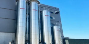
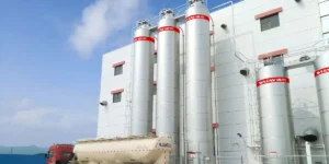
Centralized plastic resin conveying systems dominate in facilities running 10 or more processing machines, because the reduction in maintenance labor and improved material traceability typically justify the investment within two to three years. See our Wijay plastic pellet conveying product range for a full breakdown of centralized system configurations.
Why Conveying Velocity Matters More Than Throughput
Angel hair — the fine, fibrous strands of melted and re-solidified polymer created when pellets impact pipe walls at excessive velocity — is the most underestimated quality risk in plastic pellet conveying. It is not cosmetic. Angel hair accumulates in bends, valve bodies, and hopper receivers, then breaks free into the melt stream, causing black specks, surface defects, and filter contamination in finished parts.
⚠ The Angel Hair Mechanism
When pellets travel through a pneumatic conveying pipe at velocities above the threshold for the given resin, the kinetic energy of impact against bends generates enough frictional heat to soften the pellet surface. The material smears and stretches into a thin fiber — angel hair. Softer resins (LDPE, TPU, flexible PVC) are far more susceptible than rigid materials (HDPE, PP, ABS), but even nylon and engineering resins are affected when velocity is poorly controlled.
The engineering fix involves three levers, all of which must work together:
- ✓ Velocity control: Target 600–800 ft/min (180–240 m/min) for most thermoplastic pellets — substantially lower than the 2,400–3,200 ft/min typical of fine powder dilute phase systems. Variable frequency drives on the vacuum pump allow fine velocity adjustment per material type.
- ✓ Long-radius bends: Standard 90° elbows create high-impact zones. Long-radius sweeps (R/D ratio ≥10) or plug-tee style blind tees dramatically reduce impact velocity and virtually eliminate angel hair formation at bends.
- ✓ Material-matched pipe bore: Undersized pipe forces higher velocity for the same mass flow rate. Oversized pipe risks slugging at lower velocities. Pipe ID selection must account for bulk density, pellet geometry, and the actual conveying rate — not just the nameplate throughput figure.
“Running a pellet conveying system faster than necessary is not a safety margin — it is a quality defect generator.”
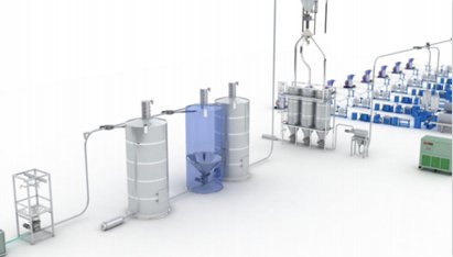
Vacuum Loaders vs. Positive Pressure: Choosing the Right Motive Force
Most plastic pellet conveying systems for injection molding operate under vacuum (negative pressure). Understanding why — and when positive pressure is the better choice — is a fundamental system design decision.
| Parameter | Vacuum (Suction) Systems | Positive Pressure Systems |
|---|---|---|
| Operating principle | Pressure differential draws pellets from source to receiver | Compressed air pushes pellets from source to destination |
| Typical conveying distance | Up to 400 m | Up to 1,000 m |
| Best for | Multiple sources → single/multiple destinations; machine-side loaders | Single source (silo/railcar) → long-distance delivery |
| Leak behavior | Air in (not product out) — safer for dust control | Product can escape at leaks — requires tight sealing |
| Equipment cost | Lower | Higher |
| Moisture risk | Ambient air drawn in — requires drying integration for hygroscopic resins | Can use dry compressed air — better for moisture-sensitive materials |
| Typical application | Injection molding plant floor, compounding lines | Silo-to-plant long-distance transfer, rail/truck offloading |
For most injection molding facilities, vacuum loaders for plastic pellets are the practical default — simpler to install, inherently safer from a dust containment standpoint, and well-suited to the multi-machine feeding topology of a typical production floor. For bulk offloading from trucks, railcars, or silos across distances beyond 100 meters, positive pressure systems are generally more appropriate.
Learn more about how we configure these systems in our plastic pellet conveying systems engineering guide.
Glass Fiber Reinforced and Specialty Pellets: Where Standard Systems Fail
Standard dilute-phase vacuum systems work well for commodity resins — PP, PE, ABS, nylon. The engineering conversation changes significantly for glass fiber reinforced (GFR) pellets, long-fiber thermoplastics, and regrind with irregular particle geometry.
GFR-specific challenge: Glass fiber reinforced pellets are highly abrasive. At dilute-phase velocities, they erode standard steel pipework, particularly at bends, within months. They also generate glass fiber dust that settles in receivers and poses both quality and respiratory hazards.
For GFR and similarly abrasive materials, dense phase conveying or low-velocity dilute phase (with ceramic-lined bends and hardened steel pipe sections) is the appropriate design basis. Dense phase systems move the pellets as moving plugs or slugs at 150–200 m/min — far below the velocity threshold for abrasive wear — at the cost of higher operating pressure (100–500 kPa) and more complex pressure regulation.
Regrind presents a different challenge: irregular particle shape and variable bulk density cause bridging in hoppers and inconsistent pickup at the conveying inlet. Agitator-equipped feed hoppers and larger pickup tube diameters are standard design provisions for regrind integration.
Where To Source Low-Maintenance Pneumatic Conveying Systems For Plastic Pellets
How Do you Size a Plastic Pellet Conveying System
Accurate system sizing is the difference between a system that runs reliably at full production rate and one that chronically underperforms. The key inputs are:
- ✓ Required throughput rate (kg/hr): Size for peak demand — not average. Factor in the simultaneous demand profile if feeding multiple machines from a centralized system.
- ✓ Bulk density of the specific resin: Pellet bulk density ranges from ~450 kg/m³ (soft foam pellets) to ~850 kg/m³ (glass-filled engineering resins). This directly determines air-to-material ratio and pipe sizing.
- ✓ Conveying distance and elevation change: Total equivalent pipe length (actual length plus equivalent length for each bend and fitting) determines pressure requirements and prime mover sizing.
- ✓ Number of machines and sequencing logic: Centralized systems must account for demand sequencing — which machines call for material simultaneously, and how the control system prioritizes competing demand.
- ✓ Moisture sensitivity of the resin: Hygroscopic materials (nylon, PET, PC, TPU) require desiccant or membrane dryer integration at the vacuum pump air inlet. This is a system design element, not an accessory.
Sizing principle: Always design conveying velocity to the minimum that reliably suspends and moves the specific pellet — not to the maximum the prime mover can produce. The headroom you need is in pressure capacity, not velocity.
What to Look for When Evaluating Plastic Pellet Conveying System Manufacturers
Not all suppliers of plastic material handling systems approach the engineering with the same rigour. When comparing options, the questions that separate a capable system from a marginal one are:
✓ Does the supplier request your actual resin bulk density and pellet geometry — or do they size from a catalog default?
✓ Can they demonstrate angel hair test data for your specific resin at the proposed conveying velocity?
✓ Do they specify pipe material and bend geometry — or leave it to the installation contractor?
✓ Is the control system architecture (PLC brand, I/O count, MES connectivity) documented in the proposal, or described vaguely as “fully automated”?
✓ Can they provide references from facilities running the same resin type at similar throughput rates?
These are not premium questions. They are baseline engineering diligence for a system that will run 24/7 in your production environment for 10–20 years.
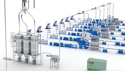
Wijay Systems Solutions for Plastic Pellet Conveying Systems
The requirements for a plastic pellet conveying system in an injection molding facility differ materially from those in a polymer compounding plant or a film extrusion line. Wijay Systems designs and supplies systems across the full plastics processing spectrum:
- ✓ Injection molding plants: Centralized vacuum conveying from silo or bag dump stations to 8–10+ machine hoppers, with PLC sequencing, cycle counting, and MES integration.
- ✓ Compounding and masterbatch: Multi-component conveying (base resin + additives + pigments) with gravimetric dosing integration and full material traceability.
- ✓ Film and sheet extrusion: High-throughput continuous feed systems with surge hopper design to maintain consistent extrusion feed rate.
- ✓ Blow molding: Dense phase or low-velocity dilute phase for HDPE and PP pellets where angel hair risk must be eliminated from food-contact or medical packaging applications.
See how we have applied these systems in the field on our plastics industry case studies page. For application-specific considerations across the plastics sector, visit our plastic industry solutions overview.
Need help optimizing your plastics conveying system?
Not sure how to replace your old compressed air system with a new one? Let us help you. The right size of the installation is crucial: not only does it help you save on energy costs, it also shortens unloading times and helps you avoid blockages. Calculating the right size of your installation is difficult and requires specific software and skills. We can help you find the optimal dilute phase pneumatic powder conveying system by offering you a free sizing calculation.
Talk to an Engineer — Not a Sales Rep
Describe your resin, your throughput, and your facility layout. We’ll come back with a plastic pellet conveying system design — including velocity calculations, pipe sizing, and a realistic equipment list — before any commercial conversation.

