Imagine your plant is running a night shift. Somewhere upstream, a rotary valve is struggling with a slightly off-spec batch of powder — particle size a touch larger than usual. By morning, you have a blocked pipe, a halted production line, and a maintenance team pulling apart bends at 6 a.m. This scenario plays out across food processing plants, chemical facilities, and battery material factories every week. And almost always, it traces back to a pneumatic conveying system that was designed for a theoretical material, not the real one.
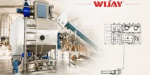
Pneumatic conveying system is not a commodity engineering task. Done well, it gives you a sealed, automated, highly flexible material transport system that can reach distances of up to 1,000 meters with minimal product loss. Done poorly, it becomes the most expensive maintenance headache in your facility.
$48B
Global pneumatic conveying market by 2032
4.6%
Annual market growth rate (IMARC, 2024)
1,000m
Maximum practical conveying distance
Why Pneumatic Conveying Systems?
Mechanical conveyors — belts, screws, bucket elevators — are workhorses. But they expose products to the environment, struggle with elevation changes, and require extensive guarding for hazardous or moisture-sensitive materials. Pneumatic systems solve a different set of problems.
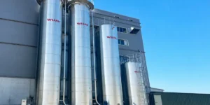
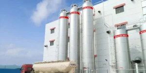
A properly designed pneumatic conveying system offers complete product enclosure, easy routing through tight spaces and multiple floors, compatibility with multiple sources and destinations on a single pipeline, and seamless integration with truck, railcar, and silo offloading. For industries handling hygroscopic chemicals, lithium battery precursors, food-grade powders, or abrasive mineral granules, these characteristics are not optional — they are the baseline requirement.
Dilute Phase vs. Dense Phase Pneumatic Conveying
Every pneumatic conveying system design decision flows from one foundational question: which flow regime is right for your material? The answer determines your pipe sizing, blower selection, pressure requirements, and ultimately, whether your product arrives at the destination intact.

Dilute Phase
- Particles are fully suspended in the airstream.
- High velocity: 700–1,000 m/min
- Low pressure: <100 kPa
- Solid-to-gas ratio up to 15:1
- Larger pipe diameters
- Lower capital cost
- Higher attrition — not for fragile materials

Dense Phase
- Slugs, plugs, or moving-bed flow
- Low velocity: ~200 m/min
- High pressure: 100–600 kPa
- Solid-to-gas ratio 100:1 or more
- Smaller pipe diameters
- Gentle on fragile or abrasive materials
- Higher system cost — requires pilot testing
The majority of industrial pneumatic conveying systems operate in a dilute phase — it is lower cost and easier to commission. However, when your material is friable (easily crumbled), abrasive, or has a high bulk density, dense-phase conveying is often the only option to achieve acceptable product quality and pipe longevity.
“The most expensive mistake in pneumatic conveying is designing for the average material, then running the worst-case batch through it.”
The Four Critical Design Parameters
Whether you are commissioning a new system or troubleshooting an existing one, pneumatic conveying system design revolves around four interconnected variables. Misread any one of them and the entire system underperforms.
1. Material characterization
Bulk density, particle size distribution, moisture content, abrasiveness, cohesiveness, and flowability all directly determine the minimum conveying velocity, the risk of pipe blockage, and the level of attrition during transport. A fumed silica with a bulk density of 1–8 lb/ft³ behaves entirely differently from iron oxide at 250 lb/ft³. Testing is not optional for unfamiliar materials.
2. Gas velocity and pressure drop
In any pneumatic conveying pipeline, pressure decreases along its length. This means the specific volume of gas increases — and so does its velocity — as the material moves toward the destination. Engineers must account for this expansion when sizing pipe diameters, especially in long runs. The minimum conveying velocity (the lowest speed at which solids remain suspended or mobile) must be maintained throughout the entire pipeline, including the end nearest the receiver.
3. Prime mover selection
Compressors, blowers, fans, and vacuum pumps each have different pressure-flow characteristics suited to specific conveying modes and distances. Dilute-phase vacuum systems are common for short, multi-source layouts, such as bag dump stations feeding a single receiver. Positive-pressure dilute-phase systems are suited to longer single-source-to-destination runs. Dense phase systems almost always require dedicated high-pressure rotary blowers or compressors with precise flow control.
4. Feeding and disengagement
Solids entering the gas stream must accelerate rapidly to conveying velocity — this acceleration zone generates the highest pressure drop in the entire system and is a common source of design error. At the destination, cyclone separators or fabric filter receivers disengage the product from the gas stream. The receiver design must match the material: fine powders need filter receivers with adequate bag area; coarse granules may use simple cyclone separation.
Key rule of thumb: The feed point and first straight section after an elbow account for the majority of pressure losses. Over-sizing the blower to compensate for a poorly designed entry is a common and costly mistake.
Where Pneumatic Conveying System Design Gets Specific
Pneumatic conveying is not a one-size-fits-all solution. Each industry imposes its own constraints, and the system design must reflect them.
Food Processing, Chemicals, Plastics & Polymers, Lithium Battery Materials, Minerals & Cement, Pharmaceuticals
In food processing, hygienic design standards (EHEDG, 3-A) govern every contact surface. Stainless steel piping, sanitary rotary valves, and CIP-compatible receiver hoppers are baseline requirements — not upgrades. In lithium battery material handling, priorities shift: lithium carbonate, graphite, and cathode powders are often moisture-sensitive and, in fine-powder form, potentially explosive. ATEX-rated equipment, nitrogen inerting, and earthing continuity across all pipe joints are critical design inputs, not afterthoughts.
Plastic pellet conveying — a high-volume application in polymer compounding and injection molding — is a classic dilute phase application, but angel hair (fine fibrous streamers created by pellet-to-wall impact) is a persistent quality and contamination issue. Managing this requires careful velocity control, smooth long-radius bends, and, for high-value resins, sometimes dense-phase conversion.
Common Design Mistakes and How to Avoid Them
- !Undersizing based on average material properties. Always design for the worst-case material batch — the highest bulk density, the largest particle size, and the highest moisture content you will ever run.
- !Ignoring elbow wear in abrasive applications. In the dilute phase at high velocity, abrasive materials erode standard elbows in weeks. Long-radius elbows, ceramic-lined bends, or plug-tee fittings are not overengineering — they are basic maintenance economics.
- !Specifying pipe diameter without accounting for gas expansion. Constant-diameter pipelines work for short runs; longer systems often benefit from stepped-diameter designs to maintain appropriate velocity as pressure drops along the line.
- !Omitting pilot testing for dense phase candidates. Dense phase flow behavior is highly material-specific. Vendor-supplied test results on a similar material are not a substitute for testing your actual product at your target conveying rate.
- !Over-specifying velocity as a safety margin. Running dilute phase systems faster than necessary accelerates pipe wear, increases particle attrition, and wastes energy. The correct safety margin is in pressure, not velocity.
How Wijay Systems Approaches Pneumatic Conveying System Design
At Wijay Systems, we design bulk material conveying systems tailored to the specific characteristics of your material, your production rate requirements, and the operational realities of your facility. We do not apply template designs to novel problems.
Our engineering process starts with material characterization — we work with your technical team to document bulk density, particle size, abrasiveness, and any special handling requirements (such as moisture sensitivity, explosion risk, and hygiene standards). From that foundation, we determine the appropriate conveying mode, size the prime mover and pipe network, and specify feed and disengagement equipment suited to your application.
We serve customers across food processing, chemical manufacturing, plastics compounding, and the fast-growing lithium battery materials sector — industries where the cost of getting the conveying system wrong is measured not just in maintenance budgets, but in product quality and production uptime.
Ready to Design a System That Actually Works?
Tell us about your material, your throughput target, and your facility constraints. Our engineers will come back with a conveying system design.Call (86) 13631706915 or email wijay@wijaygroup.com to discuss your application.

