A rotary airlock rarely gets much attention during equipment specification — it’s a small, mechanically simple component sitting at the bottom of a dust collector or feeding material into a conveying line, and on paper it looks interchangeable with any other valve of the same size. In production, that assumption gets expensive fast. The wrong rotary airlock leaks pressurized air across the valve and quietly drags down system efficiency, or it jams the moment an oversized particle gets caught between the rotor and housing, or it turns a routine product changeover into an hour of teardown that a properly specified valve would have handled in minutes. None of that is a flaw in rotary airlocks as a technology — it’s a mismatch between the specific valve design installed and the material, pressure, and cleaning requirements the application actually demands.
Rotary airlock valves are a critical component across material handling, dust collection, and pneumatic conveying systems, and understanding what separates one design from another is what turns a generic parts-catalog decision into a component that actually holds up under real production conditions.
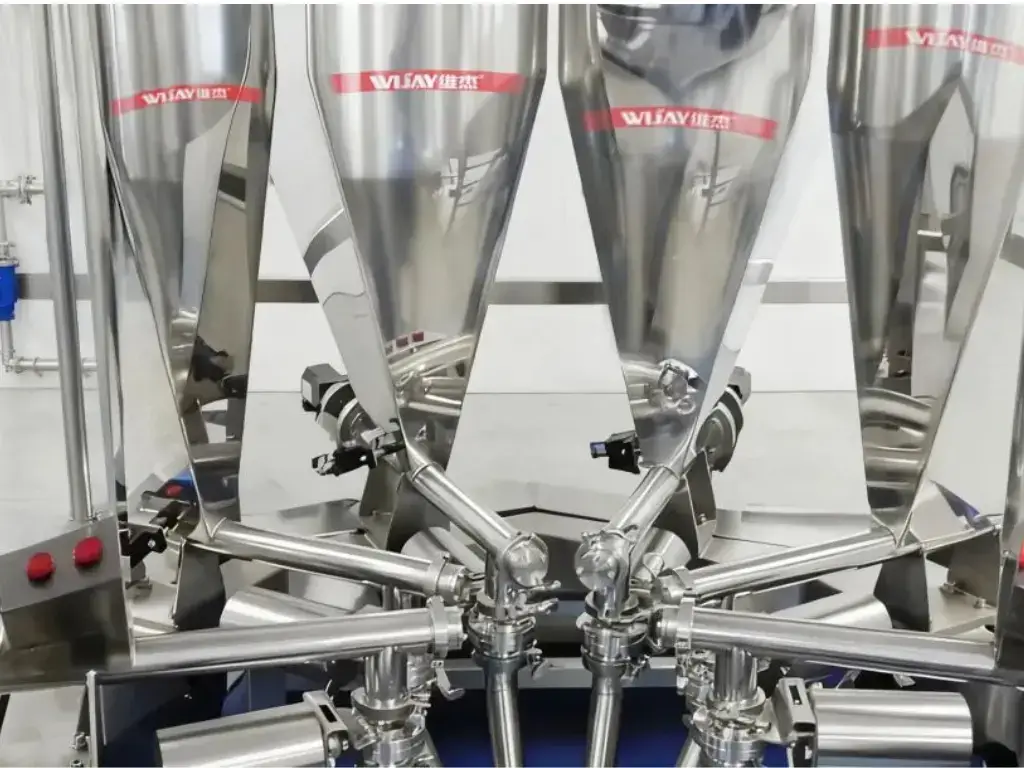
What a Rotary Airlock Actually Does
A rotary airlock valve consists of three core elements: a body, an internal rotor, and a drive package. The rotor’s shaft carries vanes that rotate inside the housing at a relatively low speed — typically 20 rpm or less — and the valve’s size combined with that rotational speed controls the material discharge rate. Because rotary valves are built with tight tolerances between the vanes and the housing, they also minimize air leakage across the valve, which is where the term “airlock” comes from. A rotary airlock can function as a feeder, an airlock, or both simultaneously, depending on the application.
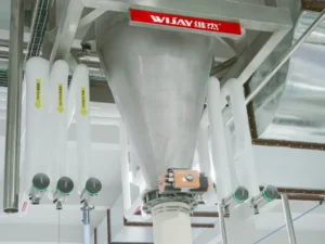
In dust collectors and pneumatic conveying systems, a rotary airlock minimizes air leakage between components above and below the valve, which typically operate at different pressure or vacuum levels. In a dust collection system, for example, the rotary airlock allows continuous product discharge without shutting down the vacuum every time accumulated material needs to be dumped.
Rotary airlocks are also essential in dilute-phase pneumatic conveying systems, where they introduce material into a pressure or vacuum pipeline stream with minimal air loss and perform the reverse function at the discharge end—separating product from the conveying air via a cyclone or filter-receiver. In systems where dust presents an explosion risk, rotary airlocks are also used in flame-barrier and explosion-isolation applications governed by NFPA (National Fire Protection Association) standards.
The market offers numerous distinct rotary airlock designs, differing by fabricated versus cast housing, standard-duty versus heavy-duty construction, straight drop-through versus side-entry configuration, blow-through versus standard discharge, and easy-clean versus standard teardown access — on top of variables in construction material, rotor design, and internal coatings. The rest of this breakdown covers the five most common configurations and exactly where each one fits.
Standard-Duty Rotary Airlock Valves
Standard-duty rotary valves typically feature a cast or fabricated body, inboard bearings, and a light-duty drive package. The internal rotor often uses rubber tips — especially on fabricated-body units — and may have as few as four rotor vanes. This design is built for gravity flow or low-pressure differential applications, such as sitting at the bottom of a dust collector.
Standard-duty valves are typically inexpensive, but that lower cost comes with real limitations. They’re not suitable for abrasive products, which will wear the valve out quickly, and they can’t withstand high temperatures or large pressure differentials. Where an application exceeds these limits, a heavier-duty rotary airlock is required instead.
Best applications: Gravity flow or very low-pressure differentials, free-flowing powders and dust, temperatures below 150°F (66°C), non-abrasive materials.
Applications to avoid: Dilute-phase conveying, food handling, abrasive products, large particles, high temperature, NFPA-rated environments.
Heavy-Duty Straight Drop-Through Rotary Airlock Valves
The straight drop-through rotary airlock has inlet and outlet flanges directly in line with each other — the inlet and outlet share the same center point. This is the most common design on the market and the workhorse of the industry.
Heavy-duty rotary airlock valves feature cast iron or cast stainless steel bodies capable of withstanding higher pressure differentials, and are frequently NFPA-rated, meaning the housing has to withstand extremely high upset pressures in the event of an explosion within the system. The rotor is likewise built from steel with eight or more vanes, held to very tight tolerances against the body — typical clearances of 0.004 to 0.006 inches (0.1 to 0.15 mm) between vane tips and housing minimize air leakage between the inlet and outlet throats.
Internal rotors are available in “open” or “closed/shrouded” designs, with fixed or adjustable rotor tips, and flat or beveled vane edges. Bearings are mounted outboard, away from the valve housing, to keep them isolated from the product flowing through the valve — a detail that prevents material from contaminating and fouling the bearings over time. Rotor shaft seals typically use a stuffing box with multiple rows of packing, air purge, or other seal arrangements to prevent material from leaking into the surrounding environment, and the drive package uses a more robust design, either directly coupled to the rotor shaft or driven through a chain or belt.
Special coatings — hard chrome, ceramic — are commonly applied to valve internals for abrasion resistance, and rotors can be built from abrasion-resistant steel or plated with specialized coatings to minimize wear and extend valve life. Internals can also be polished or coated specifically to promote product release.
Best applications: Gravity flow or higher-pressure differentials, dilute-phase conveying, elevated temperature, abrasive materials, NFPA-rated environments.
Applications to avoid: Food handling requiring frequent cleaning, large particles.
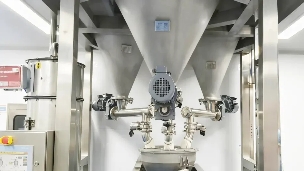
Side-Entry Rotary Airlock Valves
Beyond the standard drop-through configuration, several heavy-duty rotary airlock designs address specific application problems — starting with side-entry, sometimes called an “offset” or “pellet feeder” valve.
As noted above, rotary airlocks operate with tight tolerances, typically 0.004 to 0.006 inches. Dust, powder, and small granules pass through a standard drop-through airlock without issue at that clearance. Shearing and jamming become a problem, however, when hard, large particles enter the valve and get pinched between the rotating rotor vanes and the body’s inlet throat — an interaction that causes vibration, squealing noise, jamming, or outright damage to the material itself.
The side-entry rotary airlock is specifically engineered to eliminate this pinching problem. Its name comes from the inlet throat position, which shifts completely off-center so product enters the side of the rotor rather than the top. With this configuration, product is captured on the upswing of the rotor blades, meaning it’s constantly falling away from the shear point rather than getting trapped against it. Rotor pockets also don’t fill in this design, which further reduces the likelihood of shearing. Side-entry valves typically feature a V-shaped throat where the rotor enters the housing, minimizing the pinch point and helping push product clear. For especially demanding applications, specialized inlet adapters can further choke flow or sweep material off the rotor vanes.
The side-entry rotary airlock is particularly well suited to plastics processing — whether handling virgin pellets or regrind material in recycling operations — and is broadly useful anywhere larger, fragile particles need to move through a valve without shearing or product damage.
Best applications: Larger particles such as pellets, flake, or regrind material.
Applications to avoid: Food handling requiring frequent cleaning, NFPA-rated environments.
Blow-Through Rotary Airlock Valves
The blow-through rotary valve shares the same heavy-duty construction as the designs above, but is used exclusively in pneumatic conveying applications — both dilute-phase positive-pressure and vacuum systems. While drop-through and side-entry airlocks are suitable for feeding product into an air conveying line from above, the blow-through design works differently: instead of a standard bottom outlet, it includes two ports on the end covers, one on each side near the valve’s bottom. Rather than product dropping out the valve bottom into a separate conveying-line adapter, the conveying pipe connects directly to the valve’s end covers, and the pressurized air or vacuum stream in the conveying line flows directly through the rotor pockets.
This design is highly efficient because of the increased surface area contact between the rotor and housing, and it performs particularly well on cohesive materials that tend to hang up or pack inside rotor pockets in a standard configuration, since the conveying-line air continuously blows the material clear. Blow-through airlocks are also useful where physical height is constrained, since the design eliminates the need for transition pieces beneath the valve.
Best applications: Dilute-phase pneumatic conveying.
Applications to avoid: Food handling requiring frequent cleaning.
Easy-Clean Rotary Airlock Valves
Every rotary valve can technically be disassembled for inspection, maintenance, and cleaning, but the process is typically time-consuming — the drive linkage, whether a direct coupling or chain drive, has to be disconnected before the rotor can even be removed.
For applications requiring frequent cleaning, whether due to product changeover or hygiene requirements, easy-clean rotary valves solve this problem structurally. The design uses a two-part rotor shaft arrangement that lets the drive coupling or chain drive stay intact during cleaning. The rotor is removed from the side opposite the drive package, either by hand or with a slide-rail system that supports it during removal. Once removed, the valve internals are fully accessible for cleaning, and reassembly is simply sliding the rotor back into place and resecuring the end covers.
Best applications: Food handling, frequent cleaning requirements.
Applications to avoid: Large particles.
Making the Right Selection for Your Application
As a critical component across dust collection, material handling, and pneumatic conveying systems, choosing the correct rotary airlock design isn’t a detail to defer until installation — it’s a specification decision that determines whether the valve performs reliably for years or becomes a recurring maintenance line item. Product type, bulk density, particle size distribution, discharge rate, maximum operating temperature, pressure differential, and physical system location all factor directly into determining the correct valve type and size for a given application.
WIJAY Systems specifies rotary airlock valves as an integrated part of its bulk material handling and pneumatic conveying systems, matching valve design — standard-duty, heavy-duty drop-through, side-entry, blow-through, or easy-clean — to the material’s actual particle size, abrasiveness, temperature, and cleaning requirements, rather than defaulting to a generic valve and adjusting operations around its limitations.
FAQ
How do I know if I need a standard-duty or heavy-duty rotary airlock? Standard-duty valves suit gravity flow, non-abrasive materials, and low pressure differentials, while heavy-duty valves handle abrasive materials, higher pressure differentials, and NFPA-rated environments. WIJAY evaluates material abrasiveness, temperature, and pressure requirements before recommending a valve class rather than defaulting to whichever is cheaper upfront.
What causes a rotary airlock to jam, and which design prevents it? Jamming typically occurs when hard, large particles get pinched between the rotor vanes and the inlet throat in a standard drop-through design. A side-entry rotary airlock addresses this by shifting the inlet off-center so particles are captured on the rotor’s upswing rather than trapped against the housing. WIJAY specifies side-entry valves specifically for pellet, flake, and regrind material where shearing is a concern.
Why would you use a blow-through rotary airlock instead of a standard drop-through valve? Blow-through valves connect directly to the conveying line through ports on the end covers rather than a bottom outlet, which works especially well for cohesive materials prone to packing in rotor pockets and for installations with limited vertical clearance. WIJAY specifies blow-through configurations for dilute-phase pneumatic conveying applications where these constraints apply.
Do rotary airlocks used in food processing need a different design than industrial applications? Yes. Food handling applications requiring frequent cleaning benefit from an easy-clean rotary airlock, which uses a two-part rotor shaft to allow quick disassembly without disconnecting the drive linkage. WIJAY specifies easy-clean designs wherever sanitation and changeover frequency make standard teardown impractical.
What information does WIJAY need to specify the correct rotary airlock for a system? Key factors include product type, bulk density, particle size distribution, required discharge rate, maximum operating temperature, pressure differential, and the valve’s physical location within the system. WIJAY works through these specifications with each customer before recommending a valve design and size.