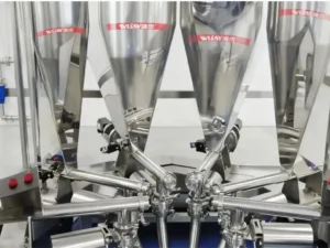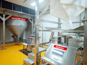
If your pneumatic conveying line is losing conveying air pressure, your feed rate is drifting, or your blower seems undersized even though the math says it shouldn’t be — check the rotary valve before you check anything else. A rotary valve for pneumatic conveying (also called a rotary airlock, star feeder, or rotary feeder) is one of the most common points of unplanned air loss in a bulk solids line, and it’s also one of the most overlooked, because the leakage doesn’t show up as a fault code. It shows up as inconsistent throughput, higher energy draw, and material that backs up at the inlet for no obvious reason.
Air leakage in a rotary valve isn’t a defect. It’s physics. Every rotary valve has a rotor spinning inside a housing, and every rotating part needs clearance to rotate without galling or seizing. That clearance is exactly where conveying air escapes. The engineering question was never “how do we eliminate leakage” — it’s “how do we size, seal, and vent the valve so leakage stays inside the tolerance your system was designed for.”
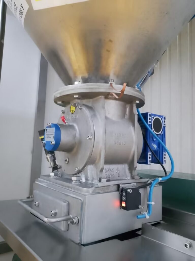
Why Rotary Valve Air Leakage Actually Matters on the Plant Floor
A few percentage points of leaked conveying air sounds trivial until you translate it into plant economics. Leaked air means your blower is doing extra work to maintain line velocity, which shows up directly on the power bill. It also means the air that should be moving material through the pipe is instead recirculating inside the valve housing, which reduces the effective feed rate and can cause material to bridge or flood at the inlet. On dust-sensitive or hygienic lines, leakage at the valve is also a containment risk — air moving in the wrong direction can push fines back out through the inlet rather than sealing them inside the conveying line.
None of this is theoretical. It’s the difference between a line that hits its rated capacity shift after shift and one that needs constant blower adjustment to compensate for a valve nobody diagnosed correctly.
The Three Leakage Paths Inside Every Rotary Valve
Before you can control leakage, you need to know where it originates. There are three distinct paths:
- Radial leakage — air escaping between the tip of the rotor blade and the valve housing.
- Axial leakage — air escaping between the edge of the rotor blade and the end plates.
- Residual (carryover) leakage — pressurized air trapped in an empty rotor pocket that gets carried back around to the valve inlet, where it can disturb the incoming material flow.
Every rotary valve for pneumatic conveying has some combination of all three, and the valve’s clearance tolerances determine how much air escapes through each path at a given pressure differential.
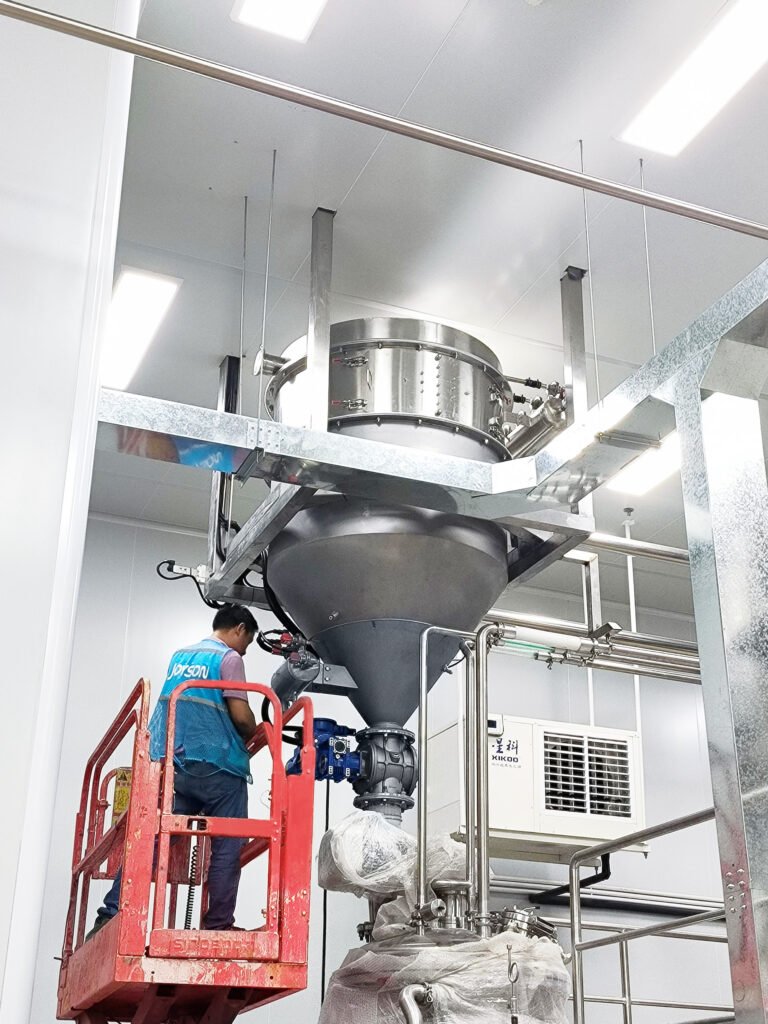
What Drives Leakage: It’s the Material, Not Just the Valve
Valve clearance is only half the equation. The bulk material being fed determines how much that clearance actually matters, and this is where a lot of generic valve specs fall short.
Flowability and Particle Characteristics
Sticky, cohesive, or interlocking materials don’t fill the rotor pocket completely. A partially filled pocket changes the effective sealing area and can increase measurable leakage even on a valve with tight nominal clearances.
Abrasiveness
Abrasive bulk solids wear the rotor tips, housing bore, and end plates over time. As wear progresses, clearances open up and leakage increases — which is why abrasion-resistant coatings like chrome, tungsten carbide, or ceramic are a sizing decision, not an upgrade you add later.
Corrosivity
Corrosive materials or process vapors attack the valve’s construction material — typically aluminum, carbon steel, or stainless — and often attack the seals faster than the rotor itself. Seal degradation from corrosion is a common, underdiagnosed source of leakage growth over a valve’s service life.
Temperature
Hot material or a hot process environment causes thermal expansion. A valve engineered for ambient conditions and operated hot will run tighter clearances than intended — or worse, contact between rotor and housing. Seal material selection has to match the actual operating temperature, not the nameplate rating.
Contamination and Purge Air Quality
The conveying gas — typically plant air or an inert gas like N2 — has to be clean and dry at the seal. Moisture, oil, or dirt introduced through the purge air degrades seal performance and accelerates leakage growth, independent of the valve’s mechanical condition.
Hardness, Degradation, and Bulk Density
Hard materials load the rotor shaft and drive components, which affects long-term clearance stability. Friable materials can degrade under rotor shear, which changes particle size distribution mid-process. And low bulk density, flood-prone powders often require an oversized valve specifically to offset pocket-fill losses under pressure — a detail that generic valve sizing tools frequently miss.
Rotor Design and Pressure Differential: The Industry Benchmark
Blade count matters more than most spec sheets suggest. A 6-blade rotor seals with only two to four blades in contact with the housing at any moment, giving leaking air only one or two barriers to cross on each side. An 8-blade rotor doubles that resistance. A 10-blade rotor, with at least six blades sealed at all times, forces air through three to four barriers per side — a meaningful reduction in measured leakage at the same pressure differential.
As a working standard: larger valves leak more air than smaller ones at the same differential pressure, and fewer blades leak more than more blades. Any system with more than two rotary valves feeding a single conveying line should include a shutoff gate above each idle valve — otherwise leaked air from non-running valves will bleed continuously into the line.
Engineering Solutions That Actually Reduce Leakage
Beyond material-specific sizing and coatings, there are proven mechanical approaches to controlling leaked air:
- Gravity discharge venting — letting leaked air vent upward through the falling material column, which has minimal effect on valve performance in low-pressure applications.
- Integral relief venting — a vent port built directly into the valve housing, which reduces overall stack height compared to an external collector.
- External leakage air collectors — capturing and venting leaked air externally to reduce its effect on valve feed rate, at the cost of additional stack height.
- Double-drop (stacked) valves — two rotary valves mounted in series, cutting leakage by roughly half. This is the most effective and most expensive option, and it has the largest impact on installation height. The lower valve must run slightly faster than the upper valve to prevent material backflow between the two.
The right approach depends on your pressure differential, available headroom, and how sensitive your process is to leaked-air disturbance at the inlet — not on a single default spec.
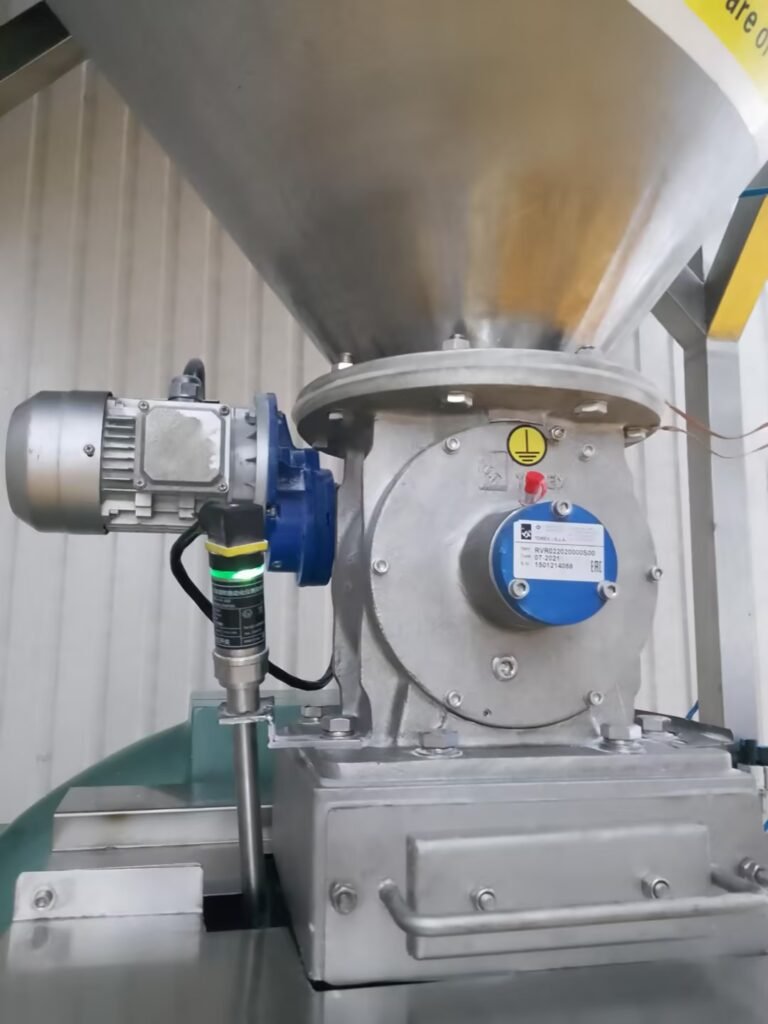
Where WIJAY Fits In
We’ve spent years engineering complete pneumatic conveying and powder handling lines — not just selling a rotary valve as an isolated component. That distinction matters here, because rotor blade count, clearance tolerance, coating selection, and venting strategy only work when they’re sized against your actual material, your actual pressure differential, and the rest of your conveying line — not a generic catalog spec.
WIJAY Systems designs fully integrated bulk material handling lines: enclosed, dust-free conveying, low-product-degradation transfer, and automated controls across pneumatic conveying, powder handling, and multi-industry processing applications. When a rotary valve is specified as part of a WIJAY line, it’s sized against your material’s flowability, abrasiveness, temperature, and pressure conditions from day one — not retrofitted after a leakage problem shows up on the plant floor.
FAQ
Is rotary valve air leakage a sign of a defective valve? No. Some leakage is inherent to how rotary valves operate — the clearances that let the rotor spin without seizing are the same clearances that allow air to pass. The engineering goal is keeping leakage within the tolerance your system was sized for, not eliminating it entirely.
How much air leakage should I expect from a rotary valve for pneumatic conveying? It depends on valve size, blade count, pressure differential, operating temperature, and material characteristics. There’s no single number — it’s why valve sizing has to be calculated against your specific application rather than pulled from a generic table.
Does a bigger rotary valve always mean more leakage? At the same pressure differential, yes — larger valves have proportionally larger clearance areas. That’s why oversizing a valve just to be safe can actually work against you on a pressure-sensitive line.
When should I consider a double-drop rotary valve setup? When your process can’t tolerate the leakage rate of a single valve at your operating pressure differential, and vent-based solutions (integral or external) aren’t sufficient. It’s the most effective leakage control method, but it comes with the highest cost and the largest installation footprint.
Can I retrofit an existing rotary valve to reduce leakage, or do I need a new one? Sometimes — recoating worn rotor tips, upgrading seals, or adding a leakage air collector can extend the life of an existing valve. But if the original valve was undersized or misspecified for your material from the start, retrofitting only buys time. Talk to your valve manufacturer or systems supplier about whether a re-spec is the better long-term fix.