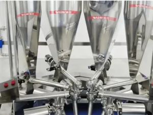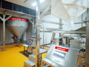
A batch of Product B shows up with trace contamination from Product A, and nobody can pin down where it happened — until someone finally pulls the diverter valve and finds product packed into a dead zone that hasn’t cleared properly in weeks. Or a seal on a valve shaft that sits eight feet up in the structure starts leaking fines onto the floor below, and getting a technician up there to fix it means a scaffold, a permit, and half a shift lost.
These aren’t edge cases. They’re the recurring failure pattern behind poorly specified directional valves in powder and bulk solids conveying — and because the valve sits mid-line, often in a hard-to-reach spot, problems here tend to get discovered late and cost more to fix than they should have.
This article breaks down what actually goes wrong with directional valve selection, the questions worth answering before you specify one, and which valve design fits which application — gravity-fed or pressurized, abrasive or free-flowing, two-way or multi-port.
What Goes Wrong When the Valve Doesn’t Match the Application
Installing a directional valve that isn’t matched to the conveyed material or the conveying method is one of the most common — and most avoidable — sources of line downtime. The recurring failure modes look like this:
- Product bridging inside the valve body, especially with cohesive or fine powders, causing flow interruption and requiring manual clearing.
- Premature seal wear, driven by abrasive material or a seal design that wasn’t rated for the operating pressure.
- Shaft-end leakage, where fines escape past the actuator shaft — a housekeeping issue at best, a contamination and safety issue at worst.
- Product holdup and cross-contamination risk, where residual material trapped in the valve body carries over into the next batch.
- Poor diverter track positioning, which sends product down the wrong path entirely and mixes batches that were never supposed to touch.
Beyond the direct production stoppage, maintenance on these valves is frequently harder than it should be simply because of where they’re mounted — mid-structure, overhead, or buried behind other equipment — which turns a routine seal replacement into a scheduling and access problem.
The Questions to Answer Before You Specify a Directional Valve
Getting this right starts before equipment selection, not after installation. The specification questions that actually determine valve performance:
- How many diverter paths does the application need?
- What internal pressure will the valve be exposed to?
- Is product holdup / carryover a critical concern for this application?
- Is the material abrasive, and what’s the particle size distribution?
- What product channel diameter is required?
- Does the seal between paths need to be absolutely tight, or is some leakage tolerable?
- What’s the angle of repose of the powder being handled?
Answering these accurately — before talking to an equipment supplier — is what separates a valve that runs for years from one that becomes a recurring line item on the maintenance log. Powder handling and conveying equipment only performs reliably when the material’s initial characteristics and behavior are fully accounted for at the design stage, not retrofitted around afterward.
Directional Valve Designs: Gravity vs. Pneumatic Applications
Directional valves fall into two broad categories based on how material moves through them.
Gravity Application Valves
These handle material falling through a duct without air pressure behind it.
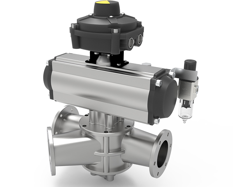
Flap diverter valves alternate feed between two lines. Sealing is typically achieved with a metal-edge gasket (some chute designs run without one), and the valve is operated manually or with a pneumatic actuator. Simple, reliable for two-way diversion, but limited to two paths.
Multi-port diverter valves, sometimes called “Sputnik”-type valves, are the only design that provides true multi-directional routing — 2, 4, 6, 8, 10 ports or more. A motor-controlled rotating tube selects which channel is connected, with sealing achieved through a telescoping tube that engages once the target position is reached. Product flow must be shut off before any tube movement — this isn’t a valve you switch under load. Common in flour milling and grain processing, where routing to many downstream destinations from a single feed point is the whole point of the equipment.
Bypass gate valves can feed a single line or both lines simultaneously — a real advantage over single-path diverters. Construction is typically two gate valves and a Y-shaped body, with the gates cylinder-actuated and position sensors available to confirm valve state.
Pneumatic Conveying Application Valves
These handle material moving at speed under positive or vacuum pressure — a fundamentally different mechanical challenge than gravity flow.
Rotary tube diverter valves connect two pneumatic conveying lines inside a fully enclosed housing. A rotary actuator tilts the connecting tube, with position sensors confirming precise alignment. An inflatable seal ring provides a complete seal, making this design suitable for both positive-pressure and vacuum systems. Switching from one channel to another must happen with no product flowing, to avoid blocking the product path. The full-bore design avoids introducing any pressure loss into the conveying line — a meaningful detail on longer runs where every pressure drop compounds.
Pinch valve bypass diverters are most commonly used in a “2-into-1” configuration rather than “1-into-2” — flow should run from two lines into one to avoid product holdup, not the reverse. This is a simple, reliable design with no moving parts in the flow path; the only required maintenance is periodic sleeve replacement.
Flexible hose diverters, typically used for pneumatic conveying of granular material, allow automatic sealed connection to multiple channels. The hose connection is made through a linear cylinder and an inflatable seal ring.
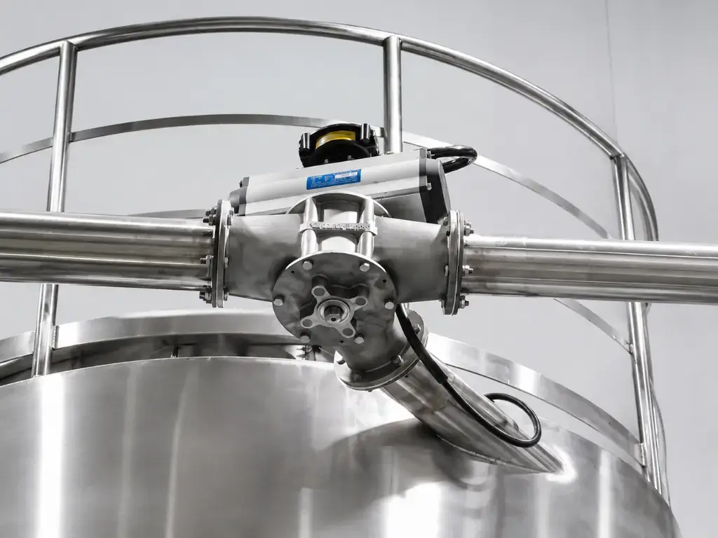
Silo-loading (chute) diverters are purpose-built for mounting at the top of a silo or hopper, ensuring product reaches the end of the pneumatic conveying line. These heavy-duty bypass valves are engineered for dense-phase pneumatic conveying of abrasive material — which means the silo structure needs to provide solid support for the valve’s weight, a detail worth flagging during structural planning, not after the valve arrives on site.
Flap-type rotary diverters consist of a machined valve body and a rotor turning on its axis, sealed with a scraping seal and actuated pneumatically. This design fits low-pressure, dense-phase pneumatic conveying of low-abrasion products — not the valve to specify for abrasive or high-pressure applications.
Matching the Valve to the Failure Mode You’re Trying to Avoid
If cross-contamination between batches is the priority, valve geometry that minimizes internal holdup — full-bore rotary tube designs, for instance — matters more than port count. If abrasive material is the constraint, valve families rated for abrasive dense-phase service (silo-loading bypass diverters, pinch valve bypass) outperform designs built for low-abrasion service. If the application genuinely needs more than two routing destinations, multi-port diverters are the only category that actually solves that problem — trying to chain multiple two-way valves together to fake multi-port routing usually just adds more failure points to the line.
The Bottom Line
Directional valve selection isn’t a commodity decision, even though it often gets treated like one. The valve sits at a structural pinch point in the line — hard to access, carrying full process pressure or gravity load, and directly responsible for keeping batches separated. Getting the specification wrong shows up as blocked product, leaking seals, cross-contaminated batches, and maintenance that costs more than it should because of where the valve lives in the structure.
WIJAY Systems specifies directional valves as part of fully integrated, enclosed pneumatic conveying and powder handling lines — matched to real material characteristics, pressure conditions, and contamination-control requirements across pharmaceutical, food, chemical, and industrial processing environments. If you’re troubleshooting a recurring diverter failure or specifying a new line, our engineering team can review your material data and routing requirements to recommend the right valve family.
FAQ
What’s the difference between a gravity directional valve and a pneumatic directional valve? Gravity valves handle material falling through a duct with no air pressure behind it, while pneumatic conveying valves must seal against positive or vacuum pressure while material moves through the line at speed — a more demanding sealing and switching requirement.
Which directional valve design is best for avoiding cross-contamination between batches? Designs that minimize internal product holdup — such as full-bore rotary tube diverters with inflatable seals — are generally the strongest choice when batch separation is the priority, since residual material trapped in the valve body is the primary cross-contamination risk.
Can a directional valve be switched while product is flowing? No, for most pneumatic and multi-port gravity designs, channel switching must happen with product flow stopped to avoid blocking the product path or damaging the valve mechanism.
What directional valve is suitable for abrasive materials? Heavy-duty silo-loading (chute) bypass diverters and pinch valve bypass diverters are typically engineered for abrasive, dense-phase pneumatic conveying service, unlike flap-type rotary diverters, which are built for low-abrasion applications.
Why are directional valves often hard to maintain? They’re frequently mounted mid-structure, overhead, or in enclosed positions within the conveying line, which makes routine seal or sleeve replacement a scheduling and access challenge rather than a quick fix.